Drive device for a finger prosthesis

Inactive Publication Date: 2005-01-27
BERGOMED
View PDF9 Cites 63 Cited by
  • Summary
  • Abstract
  • Description
  • Claims
  • Application Information

AI Technical Summary

Benefits of technology

[0009] By integrating a drive device, comprising a motor and transmission intended to transform the motor movement into finger movement, in a finger prosthesis designed to bend the finger prosthesis about a shaft in relation to a fixing, e.g. in a metacarpus prosthesis or human hand, in a movement

Problems solved by technology

This means a loss of a functioning body part with realistic appearance and a movement pattern which a prosthesis must simulate

Method used


Image

  • Drive device for a finger prosthesis
  • Drive device for a finger prosthesis
  • Drive device for a finger prosthesis

Examples


Embodiment Construction

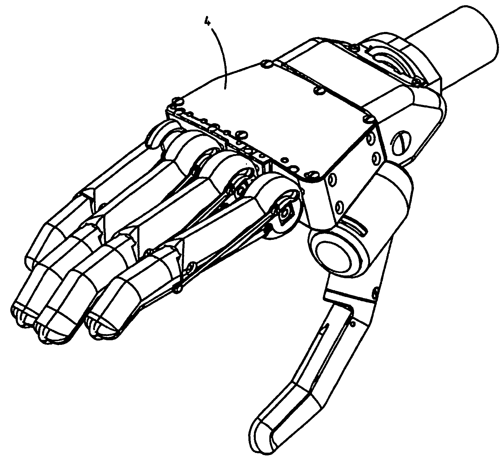
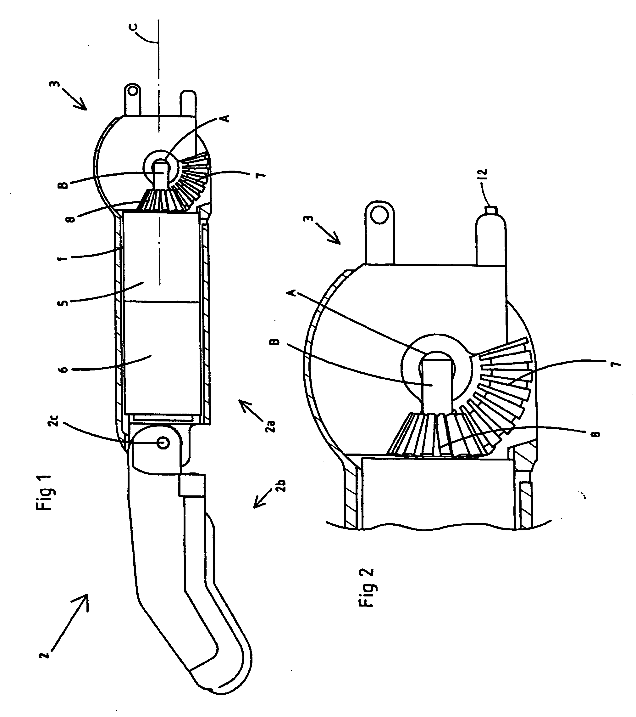
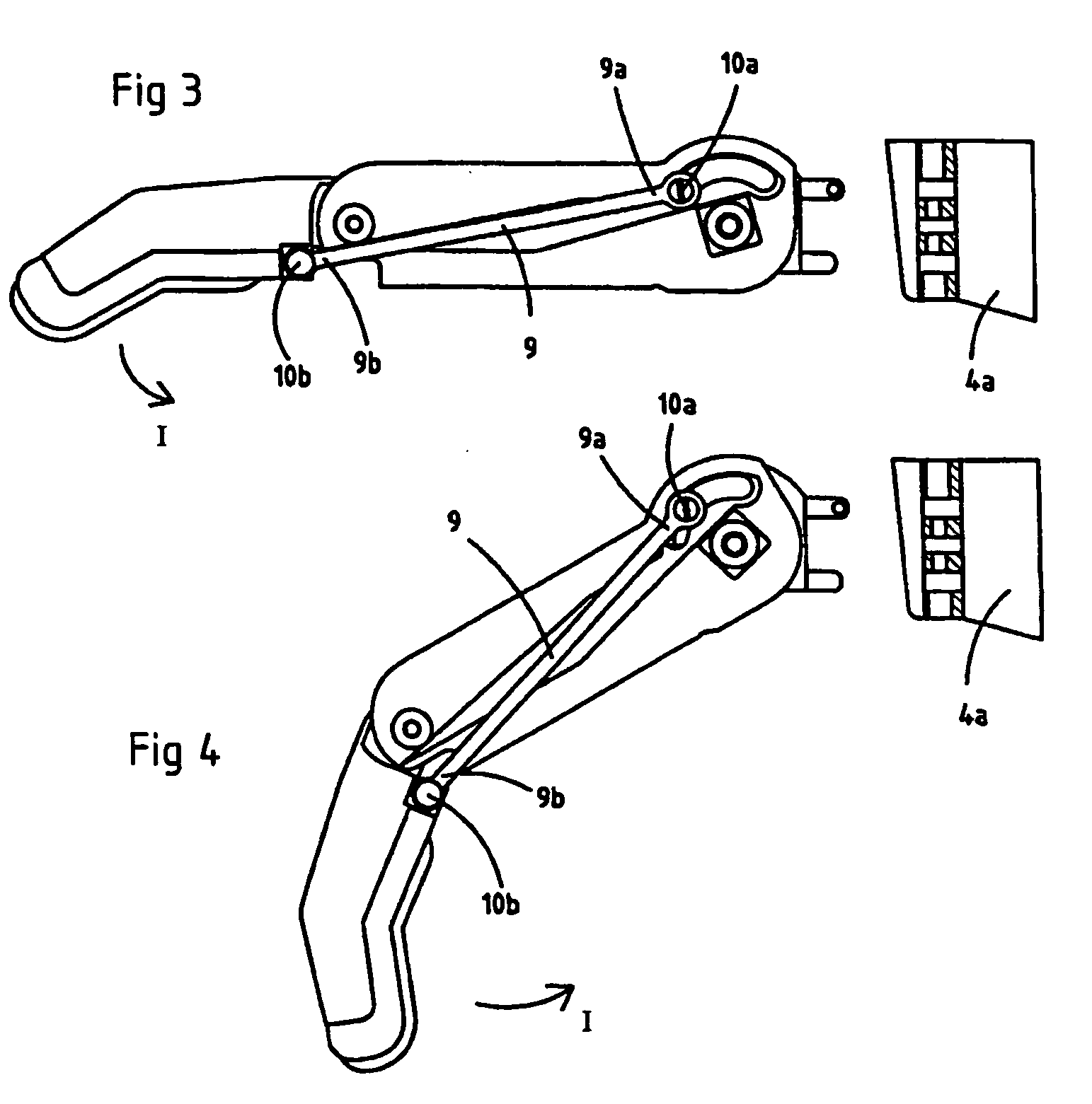
[0020] A drive device for bending a finger prosthesis is referred to generally as 1, where the finger prosthesis is referred to as 2. A fixing 3 is designed to attach the finger prosthesis to a human or artificial metacarpus 4. Substantially the entire finger prosthesis is designed to bend relative to the fixing 3 to simulate a human finger movement. Furthermore the finger prosthesis has a first part 2a and a second part 2b which are connected at a finger joint 2c so that the parts can move in relation to each other to further simulate a human finger movement. The finger prosthesis 2 is intended to bend about a shaft A placed at the fixing 3. A transmission 5 contains a gearbox 5b and an angled gear 5a. The angled gear 5a is arranged at shaft A and preferably has two bevel gear wheels 7, 8, of which the first gear wheel 7 has teeth at least partly about shaft A, and the other gear wheel 8 has teeth around an outgoing shaft B from gearbox 5b. The first gear wheel 7 in the preferred e...


PUM


Abstract

Drive device (1) for a finger prosthesis (2) of substantially natural size designed to bend the finger prosthesis (2) about a shaft (A) relative to a fixing (3) e.g. in a human or artificial metacarpus (4). The drive device (1) comprises a motor (6) which can be connected to an energy source e.g. a battery, and a transmission (5, 7, 8) intended to transform a force from the motor (6) to the finger prosthesis (2) to perform the movement. The motor (6) and transmission (5, 7, 8) are placed in the finger prosthesis (2) so that the bending shaft (A) is contained in the finger prosthesis (2) or in its extension at the fixing (3).

Description

TECHNICAL FIELD [0001] The present invention concerns a device for operating the movement of a finger prosthesis. The finger prosthesis has a natural size and is intended to be attached to a metacarpus prosthesis or a human hand. The finger prosthesis and metacarpus prosthesis are intended to replace a corresponding lost human body part. BACKGROUND OF THE INVENTION AND PROBLEM [0002] When a hand or metacarpus and fingers are lost or amputated, they can be replaced by a corresponding prosthesis. This means a loss of a functioning body part with realistic appearance and a movement pattern which a prosthesis must simulate. [0003] The prosthesis to replace the lost body part should be simple to repair and also have a cost-effective construction so that e.g. the supply of spare parts can be improved. [0004] Some known finger prostheses have a drive device with means for transmitting energy from a motor arranged at the wrist to the finger prosthesis, which means e.g. contain wires to achi...

Claims


Application Information

Patent Timeline
IPC IPC(8): A61F2/00A61F2/58A61F2/68A61F2/70
CPCA61F2/585A61F2310/00047A61F2/68A61F2/70A61F2002/30329A61F2002/30471A61F2002/30523A61F2002/30527A61F2002/30604A61F2002/5001A61F2002/701A61F2220/0025A61F2220/0091A61F2250/006A61F2/586
Inventor BRIMALM, STELLAN
Owner BERGOMED
Why Eureka
Try Eureka