Environment conservation contribution system

Inactive Publication Date: 2005-01-27
DENSO CORP
View PDF13 Cites 48 Cited by
  • Summary
  • Abstract
  • Description
  • Claims
  • Application Information

AI Technical Summary

Benefits of technology

[0005] It is a first object of the present invention to provide an environment conservation contribution system where a vehicle owner is rewarded for a decreased amount of fuel consu

Problems solved by technology

In JP-2002-230696, to retrieve the vehicle traveling state a large amount

Method used


Image

  • Environment conservation contribution system
  • Environment conservation contribution system
  • Environment conservation contribution system

Examples


first embodiment

[0033] (First Embodiment)

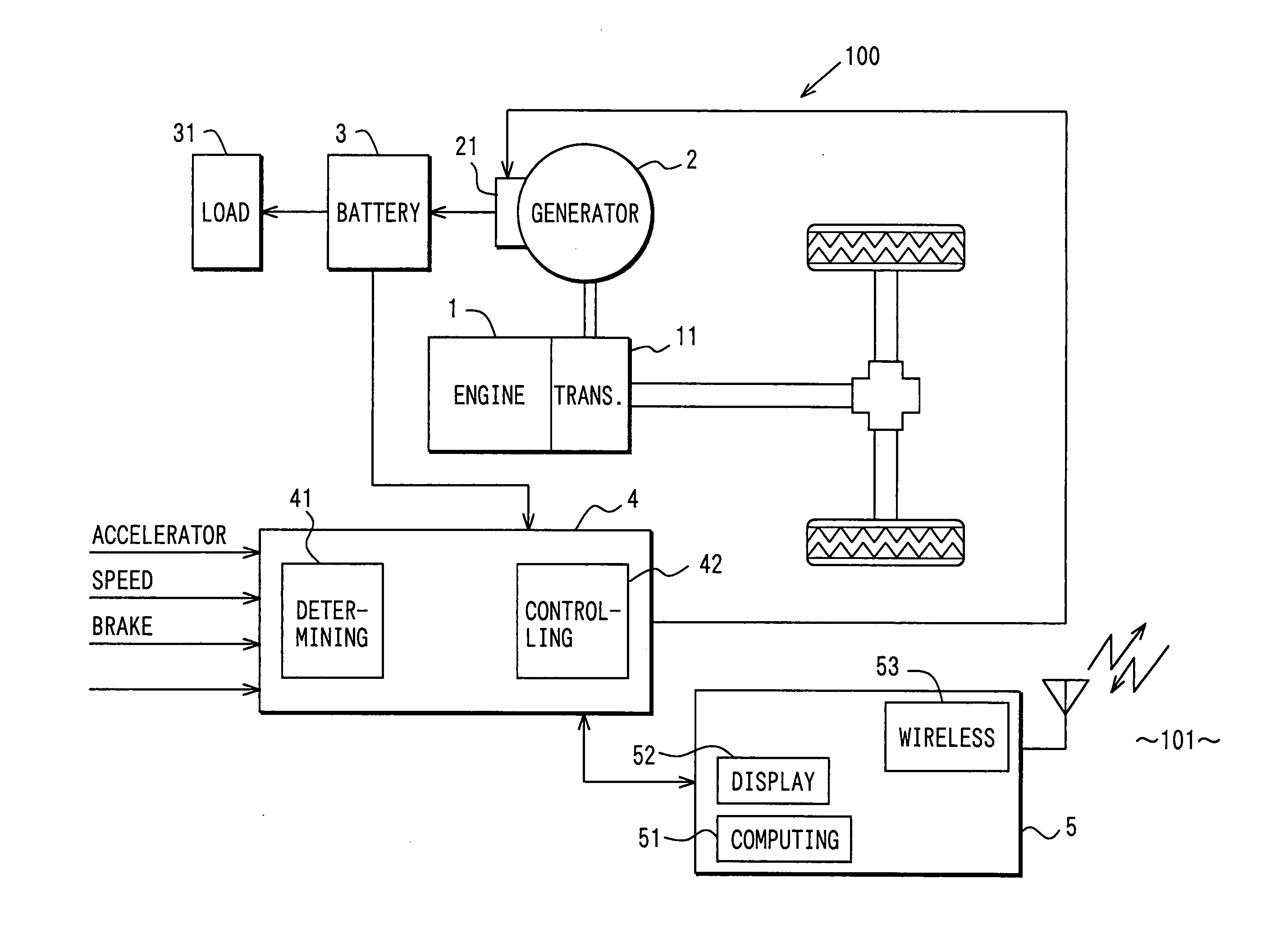
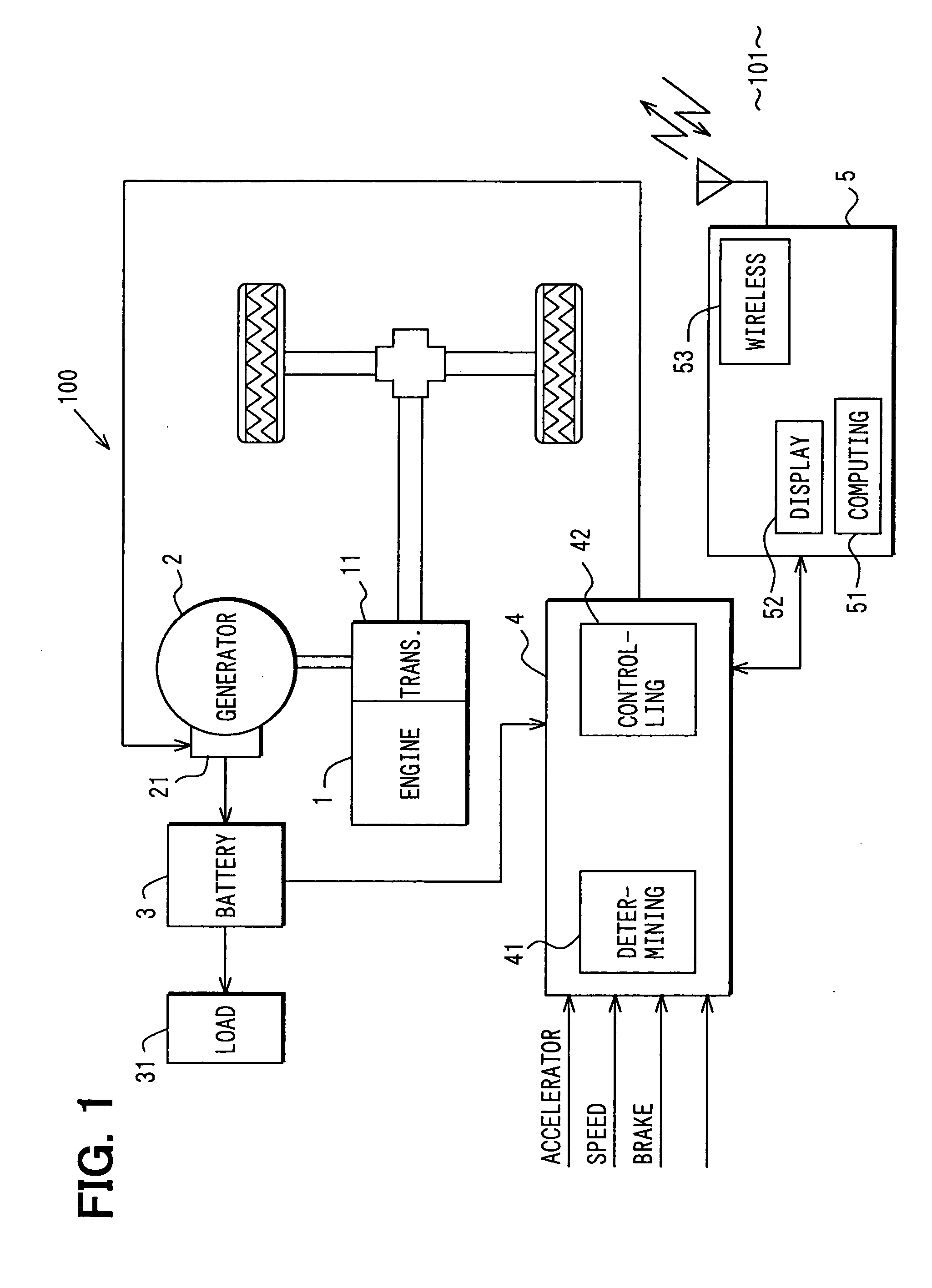
[0034] An environment conservation contribution system 100 according to a first embodiment of the present invention will be now explained with reference to FIGS. 1 to 3. The system 100 is constructed of a vehicle 101 constituting a power generation and power consumption systems, and a base station that is constructed to be communicated with the vehicle 101 and deals with data having an economic value under certain security.

[0035] The vehicle 101 includes an in-vehicle engine 1; an in-vehicle generator 2; an in-vehicle battery 3 as an electric power storage accumulating or storing electric power; a controller 4 having a regenerative generation determining means 41 for determining whether regenerative (power) generation is allowed and a generation controlling means 42 for controlling a generation amount of a generator 2; a decreased amount computing means 51; a displaying means 52; and an electronic toll collection system (ETC) in-vehicle device 5 having a wi...

second embodiment

[0070] (Second Embodiment)

[0071] An environment conservation contribution system 200 according to a second embodiment of the present invention will be now explained with reference to FIGS. 4 to 6. The system 200 is different from the system 100 in the following.

[0072] A computing means 43 is built in a controller 4, while a displaying means 40 is disposed properly in an instrument panel. In a regeneration-enabled state, a controlling means 42 increases a generation amount so that generation voltage is increased; in a regeneration-disabled state, the controlling means 42 controls the generation amount by returning the generation voltage to a normal level.

[0073] Decreased amount data computed at Step S207, relative to a (accumulated) decreased amount of fuel consumption or exhaust emission is directly written to a data card 60 storing an ID of a vehicle owner 10, by an in-vehicle writer 50 as needed. The data card 60 is disposed in the in-vehicle writer 50 so that consistency with t...

third embodiment

[0083] (Third Embodiment)

[0084] An environment conservation contribution system 300 according to a third embodiment of the present invention will be now explained with reference to FIG. 7. In the system 300, a parallel hybrid vehicle 301 includes an engine 1; a motor generator 22; an in-vehicle battery 3 as an electric power storage storing electric power; an inverter 32; a controller 4 having a state monitoring means 44; a generator controlling means 45 for controlling the motor generator 22, and a decreased amount computing means 43; a displaying means 40; a wireless terminal 53 as a data providing means. Decreased amount data is provided to the managing center 6 via wireless communications. In this embodiment, the decreased amount data is an accumulated amount relative to a decreased amount of fuel consumption or exhaust emission.

[0085] The engine 1 is operated using gasoline mounted in the parallel hybrid vehicle 301, primarily producing motive energy for traveling. The motor g...


PUM


Abstract

An in-vehicle generator is caused to start regenerative generation when the regenerative generation is possible. This regenerative generation can decrease a generation amount under a vehicle traveling state where fuel is consumed and exhaust gas is emitted, thereby decreasing a load of an engine and amounts of fuel consumption and exhaust emission. The fuel consumption or exhaust emission to be decreased is computed and transmitted to a managing center via an in-vehicle wireless terminal. The managing center provides a driver with a reward such as a service corresponding to the decreased amount of fuel consumption or exhaust emission that is computed in the relevant vehicle. This system enables the regenerative generation to be returned to the driver as an economic value, motivating the driver to decrease the fuel consumption or exhaust emission. This thereby contributes to the conservation of global environment.

Description

CROSS REFERENCE TO RELATED APPLICATIONS [0001] This application is based on and incorporates herein by reference Japanese Patent Application No. 2003-273790 filed on Jul. 11, 2003. FIELD OF THE INVENTION [0002] The present invention relates to an environment conservation contribution system contributing to global environment conservation, an in-vehicle device providing a decreased amount of fuel consumption or exhaust emission to a managing center, a regenerative generation utilization system, and a method for returning a value of regenerative generation. BACKGROUND OF THE INVENTION [0003] In JP-H8-266097 A, a technology is described that prevents an alternator from maximally generating power when an electrical load is connected so that decrease of an engine speed or decrease of driving performance can be restricted. In JP-S59-57130 A, a technology is described that returns generation power of a test motor to a public power line or a private power generation so as to recover energy....

Claims


Application Information

Patent Timeline
IPC IPC(8): B60K28/10F02D29/06B60L50/15B60W10/08B60W10/26B60W20/00B60W30/18F02D29/02G06F7/00G06Q50/00G06Q50/26H02J7/00H02J7/16
CPCB60W10/08B60W10/26Y02T10/52B60W30/18127B60W20/00Y02T10/84Y02T10/40B60W20/15
Inventor TANIGUCHI, MAKOTOKATO, AKIRATANAKA, KATSUNORI
Owner DENSO CORP
Why Eureka
Try Eureka