Method and process for configuring a premises for monitoring

a monitoring device and premises technology, applied in the field of electronic hardware and computer software, can solve the problems of inability to integrate security data from different monitoring device types to affect the system reporting and control, the use of dedicated monitoring services, and the inability to provide security guards, etc., to achieve the effect of reducing the cost of monitoring services, and ensuring the security of the premises

Inactive Publication Date: 2005-01-27
VIG ACQUISITIONS
View PDF43 Cites 260 Cited by
  • Summary
  • Abstract
  • Description
  • Claims
  • Application Information

AI Technical Summary

Benefits of technology

[0013] A system and method for configuring an integrated information system through a common user interface are provided. A user accesses a graphical user interface and selects client, premises, location, monitoring device, and processing rule information. The graphical user interface transmits the user selection to a processing server, which configures one or more monitoring devices according to the user selections.
[0014] In accordance with an aspect of the present invention, a method for configuring monitoring devices through a central interface is provided. The method can be implemented in an integrated information system in communication with a number of monitoring devices. A central server obtains a selection of at least one client associated with the integrated information system, a selection of at least one premises associated with the selected client, within the integrated information system, a selection of at least one location wherein the selected location is associated with an identifiable attribute of a premises, a selection of one or more monitoring devices associated with the selected location, and a selection of one or more processing rules associated with one or more selected monitoring device. The central server configures the integrated information system according to the selected client, premises, location, monitoring device and processing rule data. The client, premises, location, monitoring device and processing rule data selections are obtained from a common user interface.
[0015] In accordance with another aspect of the present invention, a method for configuring monitoring devices through a central interface is provided. The method may be implemented in an integrated information system in communication with a number of monitoring devices and including a computer system having a display and user input device. A computing device displays on the computer system display a set of available integrated information system clients and obtains a selection from the user input device of at least one client associated with the integrated information system. The computing device then displays on the computer system display a set of available premises corresponding to the selected client and obtains a selection from the use

Problems solved by technology

While the conventional art generally discloses utilizing multiple monitoring devices to perform various functions, conventional systems are deficient in data management functionality and integration.
Security data from different monitoring device types is generally not integrated to affect the system reporting and control.
The use of dedicated monitoring services, such as security guards is generally prohibitively expensive and unavailable for a majority of individuals and businesses.
Additionally, if the guard is distracted, absent or inattentive, a security event may go unreported.
Furthermore, the monitoring device data, such as the CCTV data, is typically available only to the dedicated premises monitor and cannot be utilized concurrently by additional users, such as a remote monitor, a quality control supervisor, the owner of the premises, or emergency or public safety authorities.
Moreover, a single security guard may not be capable of processing all of the possible monitoring data sources simultaneously, thereby reducing the effectiveness of multiple monitoring devices.
However, most external monitoring systems have a limited effectiveness in being unable to extensively provide and/or review detailed security information.
For example, most conventional external monitoring systems cannot incur the expense of providing a sufficient amount of communication bandwidth to transmit continuous video/audio feeds from every monitored premises.
In a vast majority of cases, the alarm is false and the premises owner incurs a fine for having

Method used


Image

  • Method and process for configuring a premises for monitoring
  • Method and process for configuring a premises for monitoring
  • Method and process for configuring a premises for monitoring

Examples


Embodiment Construction

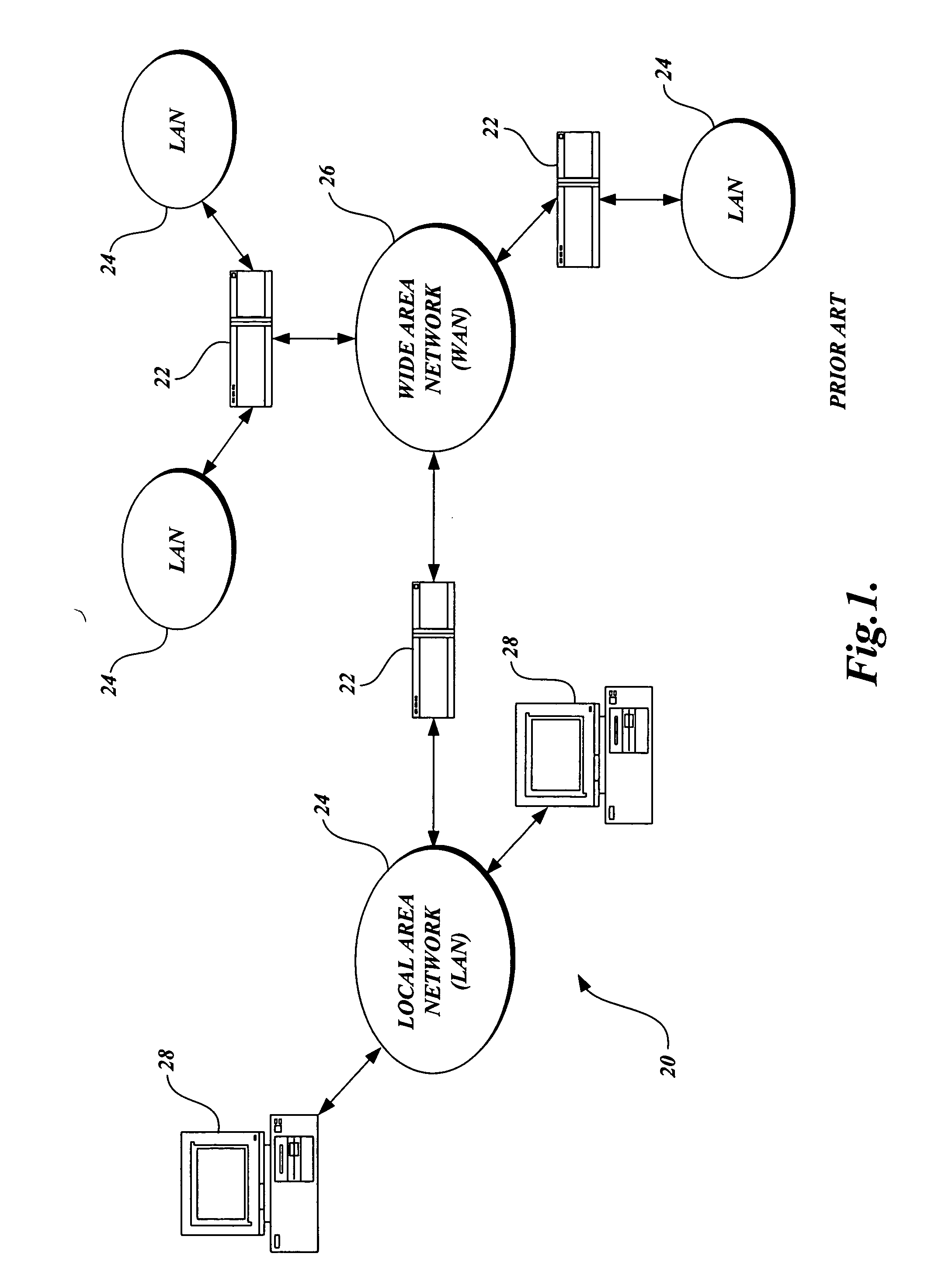
[0037] As described above, aspects of the present invention are embodied in a World Wide Web (“WWW” or “Web”) site accessible via the Internet. As is well known to those skilled in the art, the term “Internet” refers to the collection of networks and routers that use the Transmission Control Protocol / Internet Protocol (“TCP / IP”) to communicate with one another. A representative section of the Internet 20 is shown in FIG. 1, where a plurality of local area networks (“LANs”) 24 and a wide area network (“WAN”) 26 are interconnected by routers 22. The routers 22 are special purpose computers used to interface one LAN or WAN to another. Communication links within the LANs may be twisted wire pair, coaxial cable, or optical fiber, while communication links between networks may utilize 56 Kbps analog telephone lines, 1 Mbps digital T-1 lines, 45 Mbps T-3 lines, or other communications links known to those skilled in the art.

[0038] Furthermore, computers 28 and other related electronic dev...


PUM


Abstract

A system and method for configuring an integrated information system through a common user interface are provided. A user accesses a graphical user interface and selects client, premises, location, monitoring device, and processing rule information. The graphical user interface transmits the user selection to a processing server, which configures one or more monitoring devices according to the user selections.

Description

CROSS-REFERENCES TO RELATED APPLICATION(S) [0001] This application is a divisional of U.S. patent application Ser. No. 09 / 967,485, filed Sep. 28, 2001, which claims the benefit of U.S. Provisional Application No. 60 / 236,282, filed Sep. 28, 2000, entitled SYSTEM AND METHOD FOR IMPLEMENTING AN INTEGRATED INFORMATION SYSTEM, and U.S. Provisional Application No. 60 / 281,256, filed Apr. 3, 2001, entitled METHOD AND PROCESS FOR CONFIGURING A PREMISES FOR MONITORING, which are hereby incorporated by reference.FIELD OF THE INVENTION [0002] In general, the present invention relates to electronic hardware and computer software, and in particular, to a method and process for configuring a premises for the installation of monitoring devices. BACKGROUND OF THE INVENTION [0003] Generally described, electronic security systems are configured to provide a wide range of security services in both residential and commercial settings. The types of monitoring devices utilized by a particular security sys...

Claims


Application Information

Patent Timeline
IPC IPC(8): G08B7/06H04L12/24H04L12/26H04L29/06H04L29/08
CPCH04L41/22H04L69/329H04L43/045H04L43/065H04L63/0227H04L63/0263H04L63/10H04L63/1408H04L63/1416G08B7/06H04L12/2602H04L29/06H04L41/0893H04L41/18H04L67/08H04L67/36H04L67/34H04L67/025H04L67/02H04L43/00H04L67/75H04L41/0894H04L9/40G06F11/30G08B13/00
Inventor ALEXANDER, BRUCEGROSE, KARENSCHEBEL, CHRISTOPHANTAL, DAVID
Owner VIG ACQUISITIONS
Why Eureka
Try Eureka