Extraction cleaning with heating

a technology of extraction cleaning and heating, applied in the field of extraction cleaning, can solve the problems of reducing the cleanability of the applied fluid, affecting the cleaning performance of the steam system, and further hindering the cleaning performance, so as to facilitate the cleaning of the surface

Inactive Publication Date: 2005-02-03
BISSELL INC
View PDF10 Cites 71 Cited by
  • Summary
  • Abstract
  • Description
  • Claims
  • Application Information

AI Technical Summary

Benefits of technology

[0015] The cleaning fluid is preferably heated prior to the application of the cleaning fluid to the surface to be cleaned. The addition of heat to the surface facilitates cleaning of the surface because the heated cleaning fluid need not sacrifice any heat to the cooler surface to be cleaned during the cleaning process.

Problems solved by technology

However, the steam systems suffer from poor cleaning performance.
Additionally, the high power requirement for generating steam does not allow ample remaining power for running a vacuum motor, so cleaning performance is further hindered.
When heated cleaning fluid is applied to a surface that is at ambient temperature, the cleaning fluid is cooled by the carpet, thus decreasing the cleanability of the applied fluids.
Heating the cleaning fluid to a higher temperature to compensate fir the surface cooling may overcome this problem, but with an increase in energy required for the operation.
Sometimes, one encounters spots on a carpet or other surface to be cleaned that have a stain or other difficult area to clean while conduction an ordinary cleaning process.
Typically, the user must repeat the extraction process in a particular spot with limited success.

Method used


Image

  • Extraction cleaning with heating
  • Extraction cleaning with heating
  • Extraction cleaning with heating

Examples


first embodiment

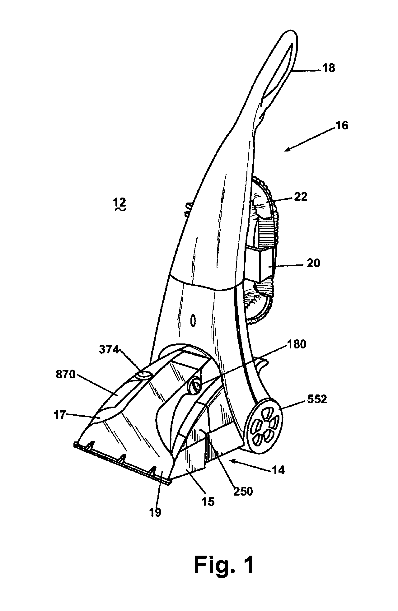
[0076] Referring now to the drawings and to FIG. 1 in particular, an upright extraction cleaning machine 12 according to the invention is shown. The machine 12 is a portable surface cleaning apparatus including a base module 14 adapted to roll across a surface to be cleaned and an upright handle assembly 16 pivotally mounted to a rear portion of the base module 14.

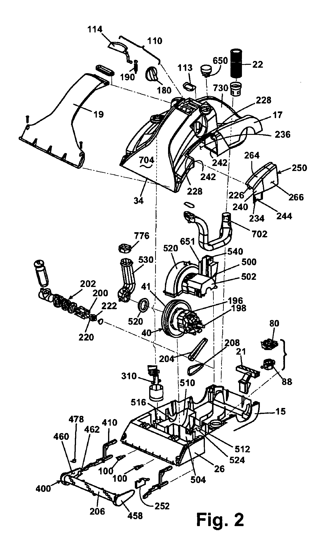
[0077] As best shown in FIGS. 1-3, the base module 14 includes a lower housing portion 15 and an upper housing portion 17, which together define an interior for housing components and a well 730 for receiving a tank assembly 50. Further, a well 732 in the upper housing portion 17 receives a detergent supply tank 870, as best shown in FIG. 3. The upper housing portion 17 receives a transparent facing 19 for defining a first working air conduit 704 and a suction nozzle 34, which is disposed at a front portion of the base module 14 adjacent the surface being cleaned for recovering fluid therefrom. The handle assembly 16 has a...

ninth embodiment

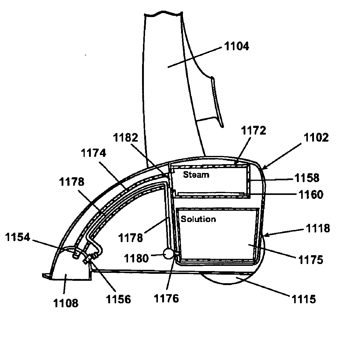
[0186] Referring now to FIGS. 30 and 31, there is illustrated the invention where like numerals are used to designate like parts. An extraction cleaner 1300 has a base 1102 that is adapted to move along a floor surface to be cleaned. A handle 1104 is pivotally mounted to the base 1102. A solution tank 1116 is mounted to a rear portion 1118 of the base 1102 and has a solution outlet 1122 which is connected to the input 1123 of pump 1120. The output 1127 of pump 1120 is connected to a solution conduit 1124 which splits in a Y to a solution conduit 1302 and a solution conduit 1314. Valves 1304 and 1316, respectively, are positioned in conduits 1302 and 1316 to control the flow of fluids through these conduits. Solution conduit 1302 is connected to a heated vapor generator 1306 that has an electrical heating element 1308 positioned therein. A heated vapor conduit 1310 is connected to an outlet of the heated vapor generator 1306 and extends along the front face of the base, terminating i...


PUM

PropertyMeasurementUnit
temperatureaaaaaaaaaa

Abstract

A portable extraction surface cleaner apparatus wherein a surface to be cleaned is heated to an elevated temperature and a cleaning fluid is applied to the surface to be cleaned sequentially or simultaneously. The cleaning fluid is removed from the surface by suction from a vacuum source. Power is applied alternatively or simultaneously to a heating element and to the vacuum source for recovering the deposited cleaning fluid.

Description

CROSS REFERENCE TO RELATED APPLICATIONS [0001] This application is a continuation-in-part of pending application Ser. No. 09 / 911,228, filed Jul. 23, 2001, which is a continuation of application Ser. No. 09 / 589,973, filed Jun. 8, 2000, which is a continuation in part of application Ser. No. 09 / 133,832, filed Aug. 13, 1998, now U.S. Pat. No. 6,131,237, which is a continuation in part of application Ser. No. 09 / 112,527, filed Jul. 8, 1998, entitled UPRIGHT EXTRACTION CLEANING MACHINE, now U.S. Pat. No. 6,167,587, and claims the benefit of U.S. Provisional Application Ser. No. 60 / 055,510, filed on Aug. 13, 1997, all of which are incorporated herein by reference in their entirety.FIELD OF THE INVENTION [0002] This invention relates to an extraction cleaning. In one of its aspects, the invention relates to an extraction cleaning machine having a solution heater for dispensing heated cleaning fluid to a surface to be cleaned. In another of its aspects, the invention relates to an extractio...

Claims


Application Information

Patent Timeline
Patent Type & Authority Applications(United States)
IPC IPC(8): A47L5/30A47L5/32A47L7/00A47L11/34A47L11/40C11D3/00C11D3/39C11D7/32C11D11/00F16K31/54F22B1/28H05B3/00
CPCA47L5/30H05B3/00A47L7/0009A47L7/0028A47L7/0038A47L7/0042A47L9/0036A47L11/34A47L11/4016A47L11/4041A47L11/4044A47L11/4083A47L11/4086A47L11/4088F16K31/54F22B1/284A47L5/32A46B9/026A47L11/4008A47L11/4075
Inventor MCDOWELL, DAVID E.HUFFMAN, ERIC C.
Owner BISSELL INC
Why Eureka
Try Eureka