Container capping control device and method and associated machine

a control device and container capping technology, applied in the direction of caps, closures using caps, applications, etc., can solve the problems of long stoppage time, high cost of stopping production, and the device is complicated without ensuring highly reliable and convenient closures, etc., to achieve convenient parameterization and convenient use.

a control device and container capping technology, applied in the direction of caps, closures using caps, applications, etc., can solve the problems of long stoppage time, high cost of stopping production, and the device is complicated without ensuring highly reliable and convenient closures, etc., to achieve convenient parameterization and convenient use.

US20050022478A1Inactive Publication Date: 2005-02-03ETAB ANDRE ZALKIN & CIE

Image

  • Container capping control device and method and associated machine
  • Container capping control device and method and associated machine
  • Container capping control device and method and associated machine

Examples


Embodiment Construction

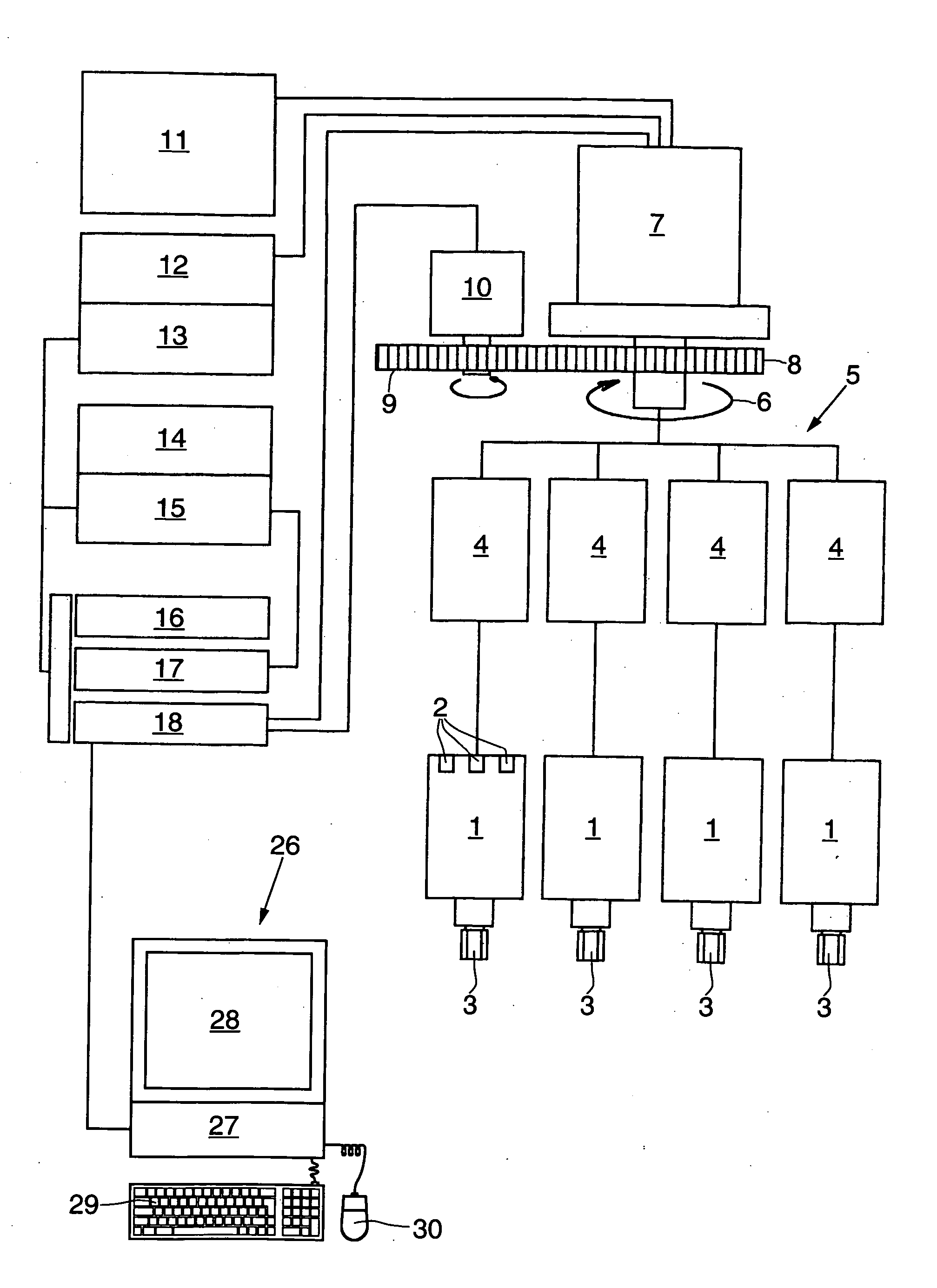
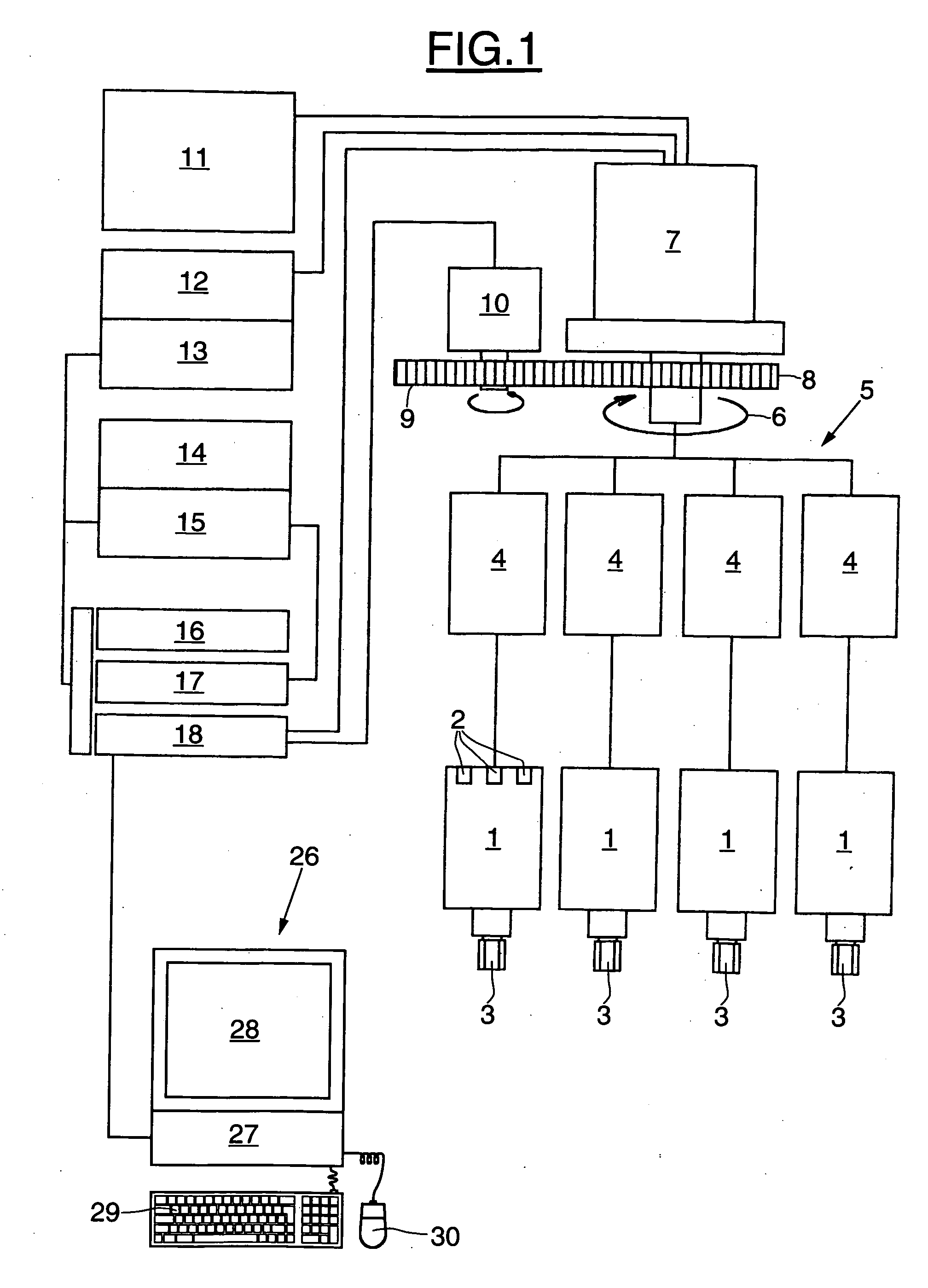
A machine for applying caps onto bottles may be installed in a bottle processing line. The bottles generally follow a circular arc trajectory in the machine. The bottles receive a cap that is screwed on or snap-fastened. The bottles afterwards exit the machine. The caps are taken up one by one by holding members which move toward the neck of a bottle, for example by virtue of a vertical downward movement. Each cap is each attached to a bottle by rotation or by snap-fastening. The caps are applied to the bottles when the bottles are following along the circular arc trajectory in the machine.

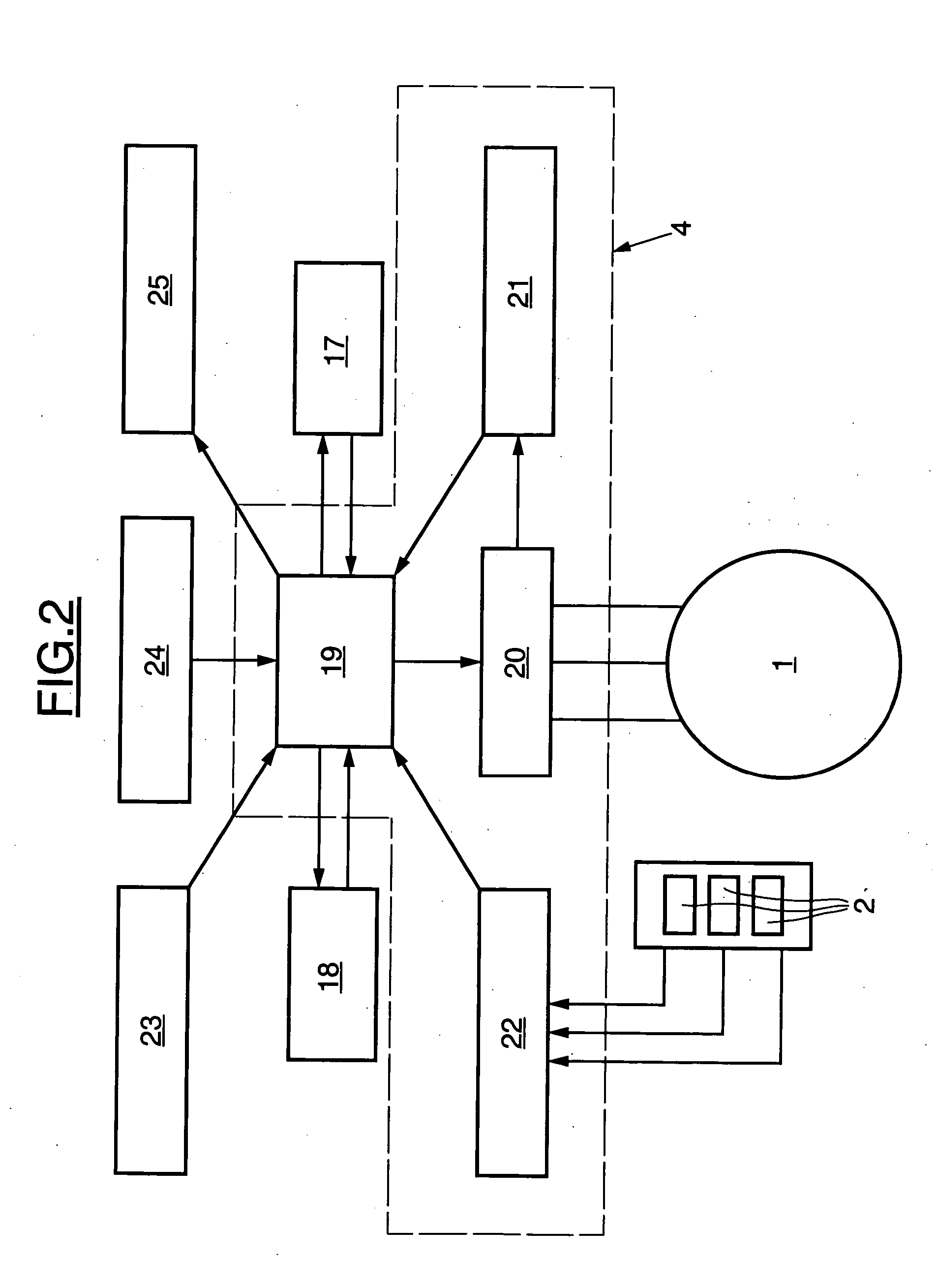
Diagrammatically, the cap screwing machine includes a plurality of motors 1 each associated with a controller 4 adapted to provide the motor with an appropriate electrical power supply. The holding members that are normally fitted to the output shaft of the motors are not shown. The motors 1 and the controllers 4 form part of a rotary assembly, usually called a turret 5. The turret may be adapted...


PUM


Abstract

A container capping control device for a machine may include at least one capping head adapted to place a closure member on a container. The capping head may include a driving motor. The device may include a calculation unit, a graphical man-machine interface and a plurality of capping programs adapted to be parameterized by means of the interface. A capping program may be adapted to control the capping head in accordance with at least one phase of rotation of the closure member when the capping program is executed by the calculation unit.

Description

BACKGROUND 1. Field of the Invention The present invention relates to the field of control of electric motors. More particularly, the present invention relates to the control of electric motors in container capping machines. The present invention may be applied in fields in which an electric motor must apply torque to an object in a precise manner, for example in the field of screwing threaded closure caps, and in the field of applying snap-fastening closure caps. 2. Description of Related Art Document EP 0 524 196 discloses a screwing device comprising a capping cone, a motor for driving rotation of the capping cone, a switching device, and a power supply. A control system comprises a torque sensor adapted to measure an instantaneous drive torque, a comparator for comparing the instantaneous torque with a closure torque of predetermined value, and a sensor for the angle of rotation of the cap receiving member adapted to be activated only when the instantaneous torque reaches th...

Claims


Application Information

Patent Timeline
03 Feb 2005
Publication
US20050022478A1
IPC
B67B3/20; B67B3/26
CPC
B67B3/261; B67B3/2033
Inventors
ZALKIN, DANIEL; OSTROWSKI, LAURENT