Turbofan case and method of making

a turbofan engine and case technology, applied in the field of turbofan case, can solve the problems of reducing the clearance of the blade tip, unable to meet the key deliverables required for such a market to be realized, and unable to meet the key deliverable requirements of such a market, so as to reduce the number of flange connections, reduce the accumulation of tolerances in the assembly, and reduce the number of blade tips

Active Publication Date: 2005-02-03
PRATT & WHITNEY CANADA CORP
View PDF42 Cites 95 Cited by
  • Summary
  • Abstract
  • Description
  • Claims
  • Application Information

AI Technical Summary

Benefits of technology

[0015] Among other things, the integral turbofan engine casing of the present invention allows for a final machining operation to the casing assembly after assembly to reduce the tolerance accumulation in the assembly. Therefore, the present invention advantageously provides a method of assembling a turbofan engine in which a smaller minimum blade tip clearance and other stack-ups are achieved. The integral casing assembly als...

Problems solved by technology

Small scale turbofan gas turbine engines are known for use in missiles in the delivery of military ordinance, however considerations such as cost-effective, affordable and efficient operation, and durability measured in thousands of hours (not minutes), have been irrelevant to their designers.
Such prior art missile engine designs, therefore, provide none of the key deliverables required for such a market to be realized.
Likewise, industrial microturbines are available, but their designs are ill-suited for use as an aircraft prime mover, for obvious considerations such as weight and size.
Scaling down of conventional civilian turbofan engines, however, also presents difficulties due mainly to the disproportionate scaling of certain factors, such as strength to weight and tolerances.
Simply scaling down these larger case designs, however, becomes problematic in “very small” turbofan engines (i.e. generally 2000 pounds thrust, and less) f...

Method used


Image

  • Turbofan case and method of making
  • Turbofan case and method of making
  • Turbofan case and method of making

Examples


Embodiment Construction

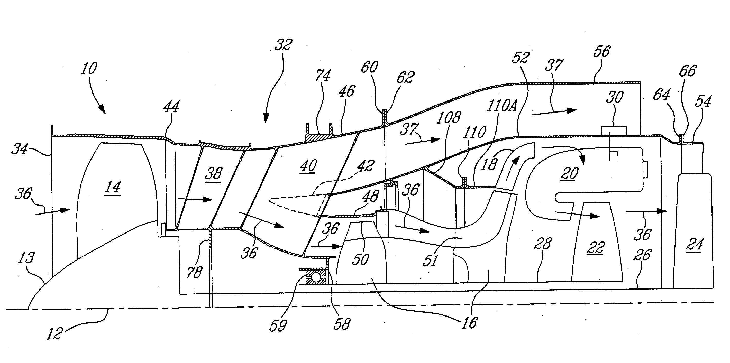
[0029] Referring to the drawings, beginning with FIG. 3, an exemplary turbofan gas turbine engine 10 according to the present invention includes in serial flow communication about a longitudinal central axis 12, a fan assembly 13 having a plurality of circumferentially spaced fan blades 14, a compressor section 16 having a plurality of circumferentially spaced low pressure compressor (LPC) blades 50 and high pressure compressor (HPC) blades 51, a diffuser 18, a combustor 20, a high pressure turbine (HPT) 22, and a low pressure turbine (LPT) 24. LPT 24 is connected to the fan assembly 13 by a first or low pressure (LP) shaft 26, and HPT 22 is connected to compressor assembly 16 by a second or high pressure (HP) shaft 28. Fuel injecting means 30 are provided for injecting fuel into the combustor 20

[0030] A generally tubular casing assembly 32 having a envelops the engine 10 and thereby defines a main flow path 36 through the core of engine 10, extending from an inlet 34 to an exhaust ...


PUM


Abstract

A casing for a gas turbine includes a fan case, an intermediate case and a gas generator case integrated with one another.

Description

THE FIELD OF THE INVENTION [0001] This invention relates to gas turbine engines, and more particularly to a case for a turbofan engine. BACKGROUND OF THE INVENTION [0002] Affordable, “personal” jet aircraft are fast becoming a reality in the general aviation market, very small turbofan engines are required for power. Such aircraft require “very small” turbofan engines (i.e. 2000 pounds thrust and under) which can be economically operated by the general aviation pilot. Small scale turbofan gas turbine engines are known for use in missiles in the delivery of military ordinance, however considerations such as cost-effective, affordable and efficient operation, and durability measured in thousands of hours (not minutes), have been irrelevant to their designers. Such prior art missile engine designs, therefore, provide none of the key deliverables required for such a market to be realized. Likewise, industrial microturbines are available, but their designs are ill-suited for use as an ai...

Claims


Application Information

Patent Timeline
IPC IPC(8): F01D5/22F01D25/24F02K3/06
CPCF01D5/22F01D25/24Y02T50/673Y02T50/671F02K3/06Y02T50/60F01D25/162
Inventor ELEFTHERIOU, ANDREASLOBO, KEVIN WALTERWEINBERG, MAURICELIU, QUANTAI
Owner PRATT & WHITNEY CANADA CORP
Why Eureka
Try Eureka