Detection of metal disturbance in a magnetic tracking system

a magnetic tracking system and metal disturbance technology, applied in the field of noncontact tracking of objects, can solve the problems of inconvenient computation, inability to converge, and no longer precise mathematical models, and achieve the effect of enhancing the accuracy of an electromagnetic tracking system

Active Publication Date: 2005-02-03
BIOSENSE WEBSTER INC
View PDF99 Cites 46 Cited by
  • Summary
  • Abstract
  • Description
  • Claims
  • Application Information

AI Technical Summary

Benefits of technology

Embodiments of the present invention provide methods for enhancing the accuracy of an electromagnetic tracking system, by detecting the presence and effect of field-responsive articles, such as metal tools, in the vicinity of the object being tracked. Such systems typically comprise one or more radiator coils, which produce energy fields in the vicinity of the object. One or more sensor coils generate signals that are indicative of spatial coordinates of the object. A system controller analyzes the signals in order to compute the object coordinates by fitting the signal amplitudes to a mathematical model of the energy fields produced by the radiator coils.

Problems solved by technology

When the fields are perturbed by an article in the detection volume, the mathematical model is no longer precisely correct, and the computation of the coordinates may therefore fail to converge.
Consequently, the coordinate computation may still converge at some frequencies despite the perturbation (and may yield an inaccurate result).

Method used


Image

  • Detection of metal disturbance in a magnetic tracking system
  • Detection of metal disturbance in a magnetic tracking system
  • Detection of metal disturbance in a magnetic tracking system

Examples


Embodiment Construction

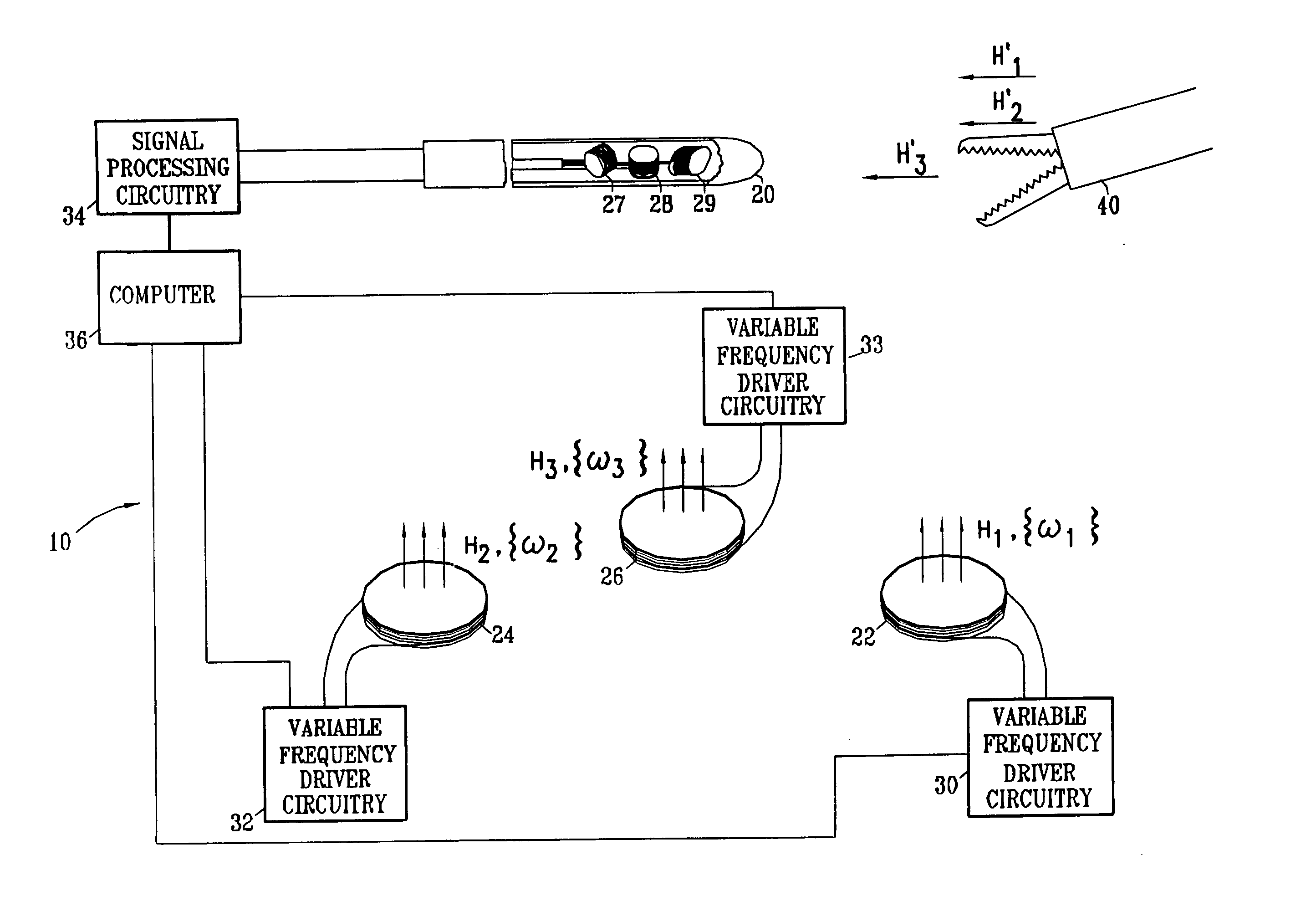
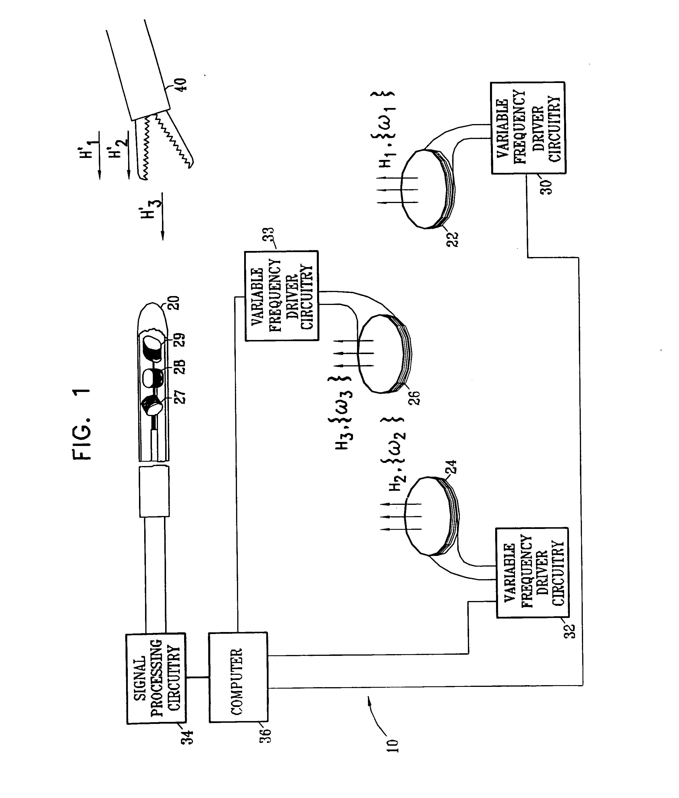
Reference is now made to FIG. 1, which schematically illustrates a system 10 for tracking a probe 20, such as a catheter for medical use, in accordance with an embodiment of the present invention. Similar systems are described in the above-mentioned U.S. Pat. Nos. 5,319,199, 6,147,480 and 6,373,240 and Patent Publication US 2002 / 0065455 A1. Elements of the description are repeated here for the sake of clarity and completeness.

System 10 comprises a plurality of radiator coils 22, 24 and 26, which are placed in known positions and orientations. The radiator coils are driven by variable-frequency driver circuits 30, 32 and 33 to generate respective magnetic fields {right arrow over (H)}1, {right arrow over (H)}2 and {right arrow over (H)}3, at respective sets of frequencies {ω1}, {ω2} and {ω3}, in the vicinity of probe 20. Typically, sets {ω1}, {ω2} and {ω3} comprise frequencies in the approximate range of 100 Hz-20 kHz, although higher and lower frequencies may also be used. The se...


PUM


Abstract

A method for tracking an object includes producing energy fields at a plurality of different frequencies in a vicinity of the object, and receiving signals that are generated at a location of the object at the different frequencies in response to the energy fields. Multiple computations are made of spatial coordinates of the object based on the signals received at the different frequencies. Convergence of the computations is tested in order to ascertain whether the energy fields have been perturbed by an article in the vicinity of the object.

Description

FIELD OF THE INVENTION The present invention relates generally to non-contact tracking of objects using magnetic fields, and specifically to detecting the effect of an intruding field-responsive article in the field. BACKGROUND OF THE INVENTION Non-contact electromagnetic tracking systems are well known in the art, with a wide range of applications. U.S. Pat. No. 5,391,199, to Ben-Haim, whose disclosure is incorporated herein by reference, describes a system for generating three-dimensional location information regarding a medical probe or catheter. A sensor coil is placed in the catheter and generates signals in response to externally-applied magnetic fields. The magnetic fields are generated by three radiator coils, fixed to an external reference frame in known, mutually-spaced locations. The amplitudes of the signals generated in response to each of the radiator coil fields are detected and used to compute the location of the sensor coil. Each radiator coil is typically driven...

Claims


Application Information

Patent Timeline
Patent Type & Authority Applications(United States)
IPC IPC(8): G01S5/04A61B5/06A61B17/00A61B19/00
CPCA61B5/06A61B2019/5251A61B2017/00039A61B5/062A61B2034/2051G01S5/16
Inventor GOVARI, ASSAF
Owner BIOSENSE WEBSTER INC
Why Eureka
Try Eureka