Display device using current driving pixels

a technology of current driving pixels and display devices, applied in the field of display devices, can solve the problems of increasing the cost of display devices, and achieve the effect of eliminating inaccurate output current signals

Active Publication Date: 2005-02-03
SANYO ELECTRIC CO LTD
View PDF12 Cites 18 Cited by
  • Summary
  • Abstract
  • Description
  • Claims
  • Application Information

AI Technical Summary

Benefits of technology

[0015] Provision of the compensation circuit in this manner enables the elimination of inaccurate output current signals, even when the threshold voltage of the current conversion circuit is different from a predetermined voltage.

Problems solved by technology

Providing an additional IC including the voltage-current conversion circuit requires that the IC be separately prepared, entailing development and production costs, and therefore increasing the cost of the display device.

Method used


Image

  • Display device using current driving pixels
  • Display device using current driving pixels
  • Display device using current driving pixels

Examples


Embodiment Construction

[0029] Embodiments of the present invention will next be described with reference to the accompanying drawings.

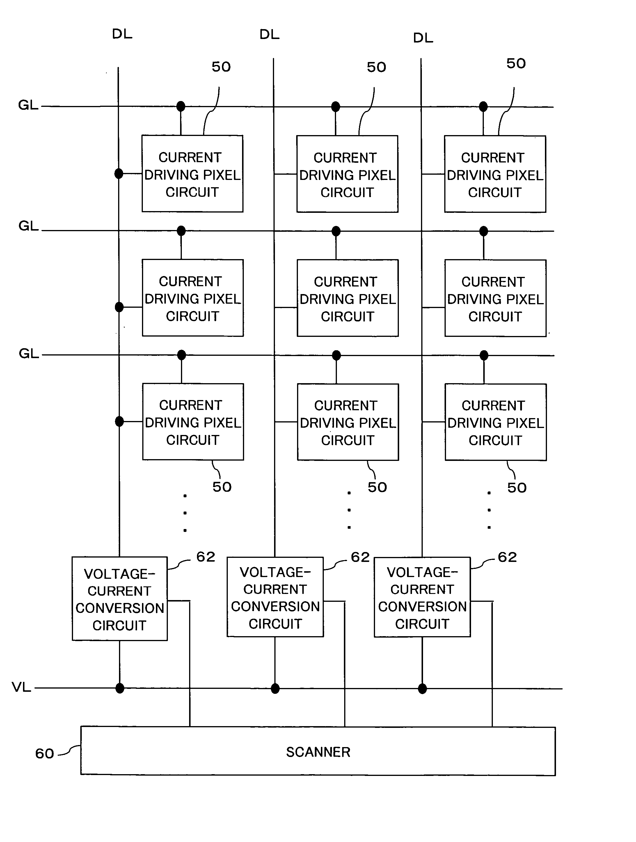
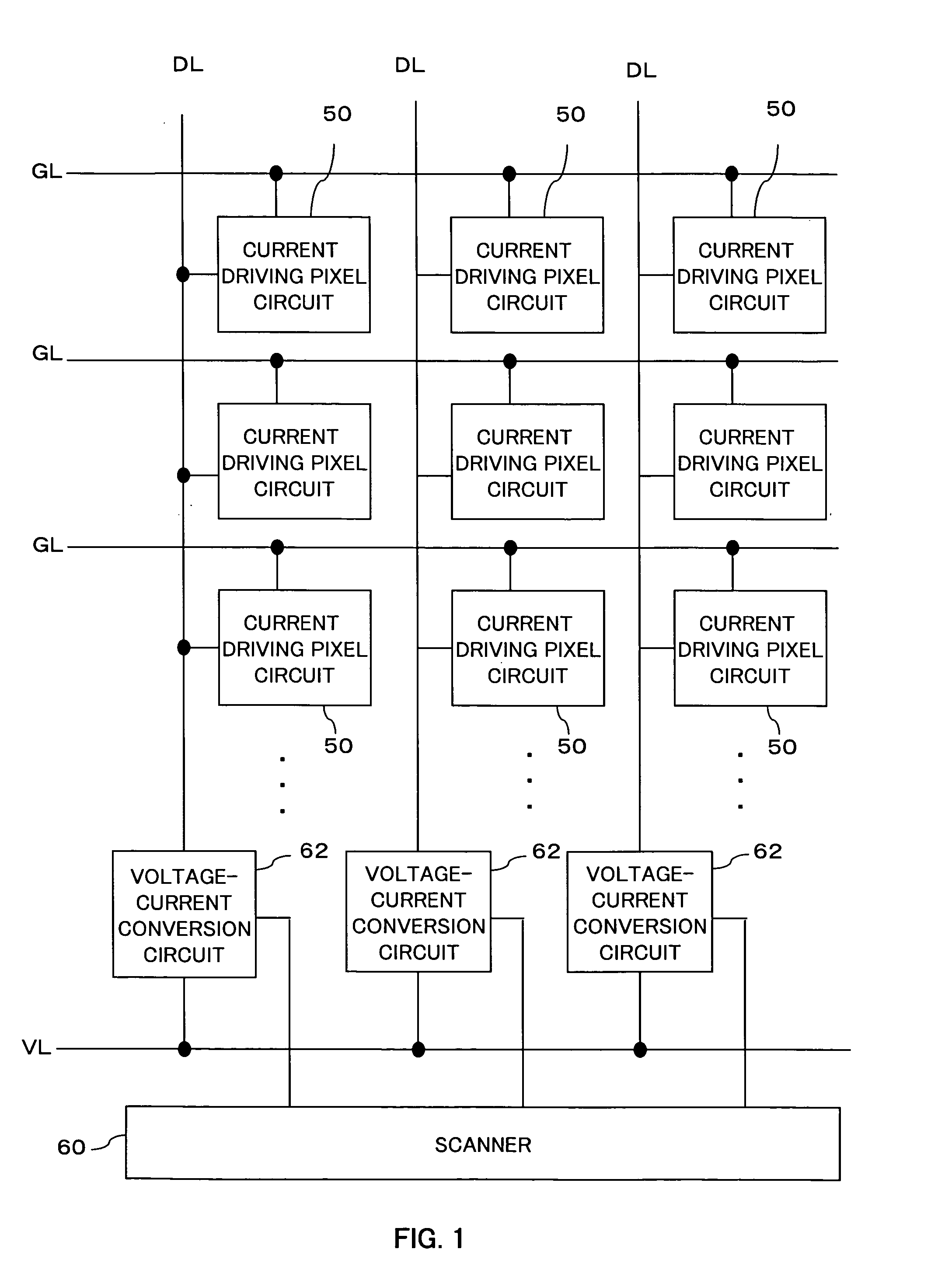
[0030]FIG. 1 shows an overall configuration of an embodiment in which current driving pixel circuits 50 are arranged in a matrix to form a display region. The pixel circuit 50 including an organic EL element and a TFT controlling the driving of the organic EL element, as described hereinafter, is deposited on a glass substrate.

[0031] A horizontal scanner 60 and a vertical scanner (not shown) for driving the current driving pixel circuit 50 are disposed around the periphery of the substrate. These scanners are basically formed on the same substrate through the same process as the TFT and the like in the pixel circuit.

[0032] Data lines DL are arranged along a column direction (vertical direction) of the pixel circuit 50, each connected to a video signal line VL through a voltage-current conversion circuit 62, which receives a control signal from the horizontal scanner 60. ...


PUM


Abstract

A video signal line receives a voltage video signal. The supplied voltage video signal is provided to a voltage-current conversion circuit in a corresponding column. The voltage-current conversion circuit converts the voltage video signal into a current signal, and supplies the current signal to a corresponding pixel circuit. Each voltage-current conversion circuit includes an output transistor for supplying current in accordance with the voltage video signal, and a compensation circuit for compensating for variations in threshold of the output transistor.

Description

CROSS-REFERENCE TO RELATED APPLICATIONS [0001] The priority applications Numbers 2003-177262 and 2003-177264 upon which this patent application is based are hereby incorporated by reference. BACKGROUND OF THE INVENTION [0002] 1. Field of the Invention [0003] The present invention relates to a display device for presenting a display by supplying a current video signal converted from a voltage video signal to a pixel circuit. [0004] 2. Description of the Related Art [0005] Electroluminescence (hereinafter referred to as “EL”) display devices using a self-emissive EL element as an emissive element for each pixel offer advantages of, for example, self-emissive properties and reduced power consumption, and are therefore attracting attention for their potential to replace liquid crystal display devices (LCDs) and CRTs. [0006] Active matrix type EL display devices wherein a switch element, such as a thin film transistor (TFT) for individually controlling EL elements, is provided for each p...

Claims


Application Information

Patent Timeline
Patent Type & Authority Applications(United States)
IPC IPC(8): G09F9/30G09G3/30G09G3/32
CPCG09G3/3241G09G3/3283G09G2300/0842G09G2330/028G09G2310/027G09G2310/06G09G2300/0861G09G3/30G09F9/30
Inventor SANO, KEIICHI
Owner SANYO ELECTRIC CO LTD
Why Eureka
Try Eureka