Optical apparatus and laser display apparatus having laser beam scanner each

a technology of laser display and optical equipment, which is applied in the scanning details of television systems, instruments, television systems, etc., can solve problems such as safety threats

Inactive Publication Date: 2005-02-03
SONY CORP
View PDF2 Cites 43 Cited by
  • Summary
  • Abstract
  • Description
  • Claims
  • Application Information

AI Technical Summary

Benefits of technology

[0016] With the above-outlined laser display apparatus in operation, the fault detection block may detect a scanner system failure based on the information sensed by the angle sensor. In that case, the

Problems solved by technology

In such a case, the dose of the laser beam per unit projected ar

Method used


Image

  • Optical apparatus and laser display apparatus having laser beam scanner each
  • Optical apparatus and laser display apparatus having laser beam scanner each
  • Optical apparatus and laser display apparatus having laser beam scanner each

Examples


Embodiment Construction

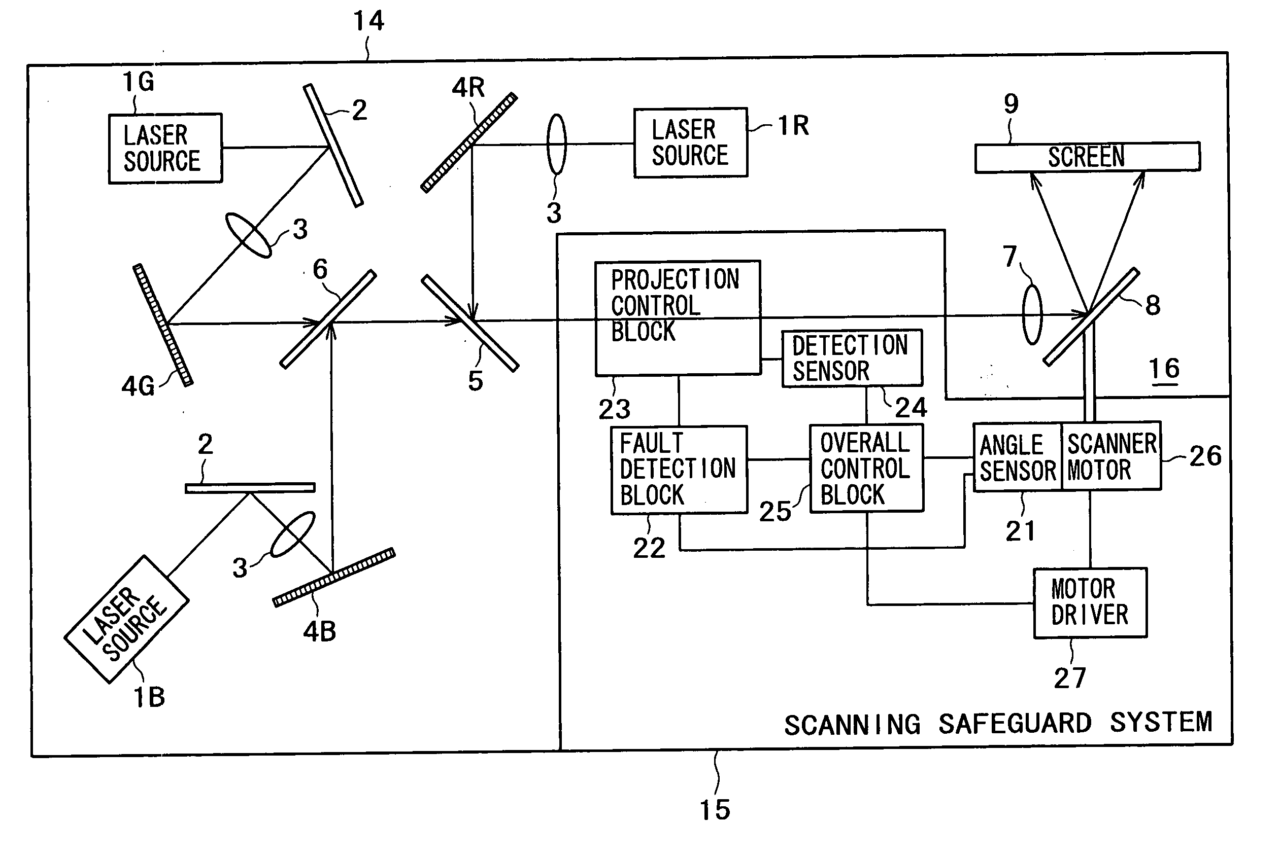
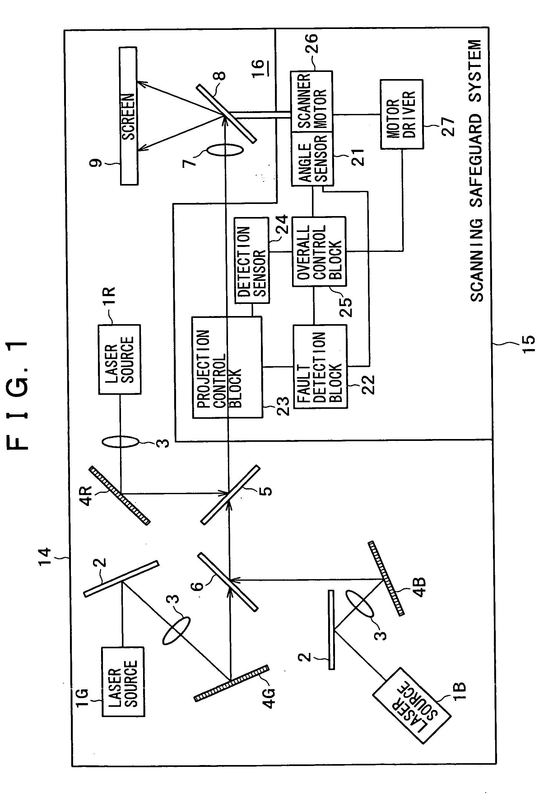
[0037] Described below with reference to the schematic block diagram of FIG. 1 is a projection apparatus accommodating an optical apparatus 16 and a laser display apparatus 14 each equipped with a laser beam scanner according to the invention. The setup of FIG. 1 includes: laser sources 1R, 1G and 1B generating laser beams of red, green and blue respectively; condensing lenses 3 furnished in combination with the laser sources; and light modulators 4R, 4G and 4B composed of GLV (grating light valve) each and used to obtain a one-dimensional projected optical image.

[0038] Optical images modulated by the light modulators 4R, 4G and 4B in keeping with a projected optical image are merged by dichroic mirrors 5 and 6. The merged image reaches a scanner 8 through a projection lens 7. With its reflected light, the scanner 8 scans a screen 9.

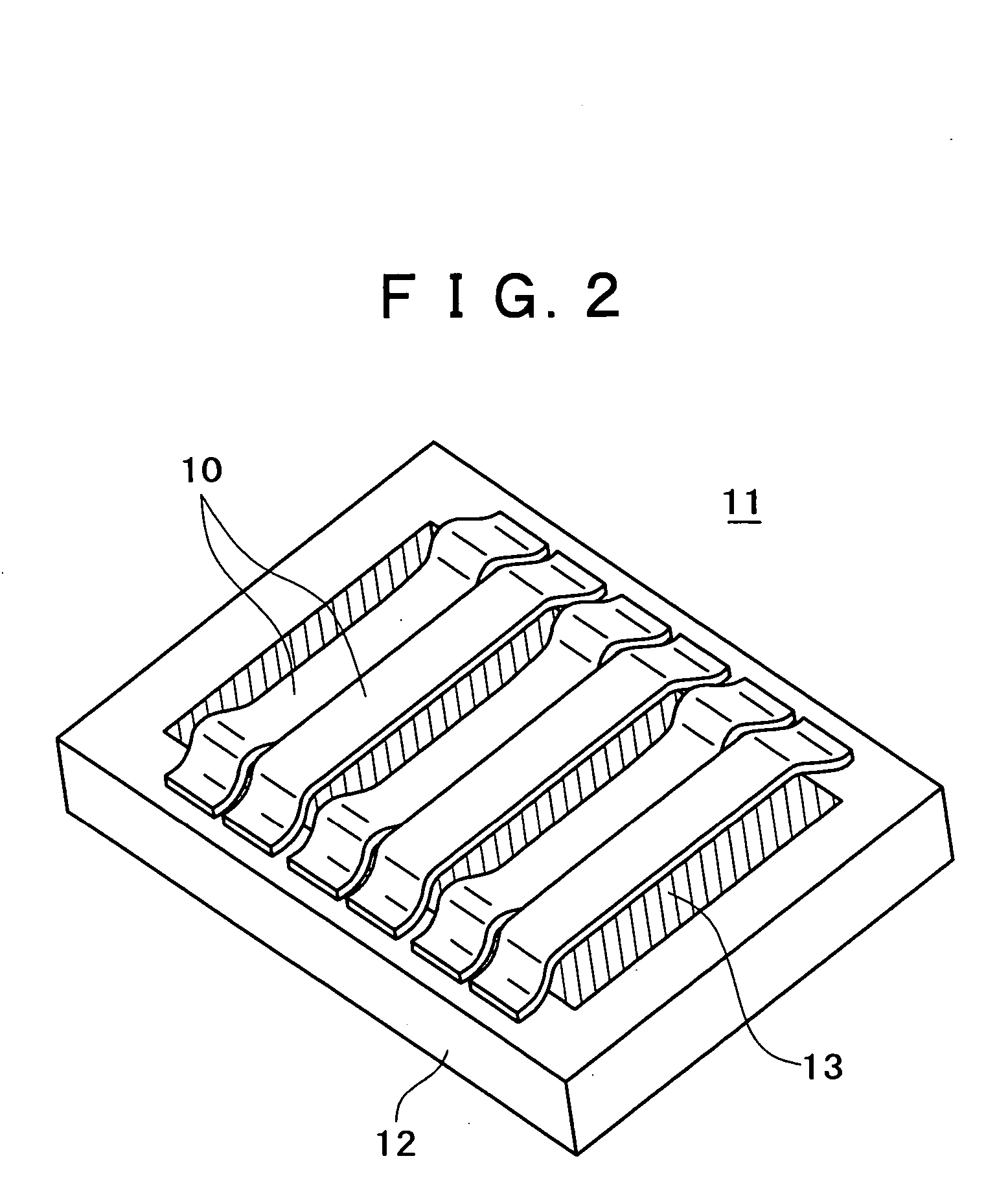
[0039] The light modulators 4R, 4G and 4B are typically constituted either by a blazed type optical diffraction grating or by GLV made of a micro ribb...


PUM


Abstract

An optical apparatus is disclosed which has a scanner for scanning a predetermined area with a laser beam. The optical apparatus comprises: a laser source; a scanner having a scanning mirror for causing a laser beam generated by the laser source to scan; an angle sensor for sensing angles of the scanning mirror of the scanner; a fault detection block for determining whether the scanning mirror operates safely and normally based at least on angle information coming from the angle sensor; and a projection control block for controlling projection of the laser beam based on fault detection information coming from the fault detection block.

Description

BACKGROUND OF THE INVENTION [0001] The present invention relates to an optical apparatus and a laser display apparatus each having a laser beam scanner. [0002] Today, devices and apparatuses handling laser beams are required to comply with rigorous safety standards. The equipment utilizing laser beams includes light show devices and bar code readers used by POS (point of sale) systems. Each of these devices is furnished illustratively with a scanner for scanning a target area with a laser beam. [0003] Another typical laser beam device is a display apparatus as part of theater-use projection equipment for projecting images to be viewed by a large audience. In order to acquire a brightly projected image on a large screen, the display apparatus first forms a one-dimensional optical image using one-dimensional light modulators and then causes the optical image thus formed to be scanned perpendicularly for projection, whereby a two-dimensional optical image is projected. [0004] Where the...

Claims


Application Information

Patent Timeline
IPC IPC(8): G02B26/10G02B26/08H04N3/08
CPCG02B26/0808
Inventor SAKAI, YOSHITSUGU
Owner SONY CORP
Why Eureka
Try Eureka