Optical-scanning examination apparatus

a scanning examination and optical technology, applied in the direction of optical radiation measurement, luminescent dosimeters, instruments, etc., can solve the problems of reduced ease of use, cumbersome operation, and difficulty in detecting or focusing on the examination site, and achieve the effect of simple configuration

Active Publication Date: 2005-09-29
EVIDENT CORP
View PDF5 Cites 55 Cited by
  • Summary
  • Abstract
  • Description
  • Claims
  • Application Information

AI Technical Summary

Benefits of technology

[0009] The present invention has been conceived in light of the circumstances described above. An object of the present invention is to provide an optical-scanning confocal microscope apparatus having a simple con...

Problems solved by technology

As a result, this apparatus suffers from the drawback that it is difficult to detect or focus on the examinat...

Method used


Image

  • Optical-scanning examination apparatus
  • Optical-scanning examination apparatus
  • Optical-scanning examination apparatus

Examples


first embodiment

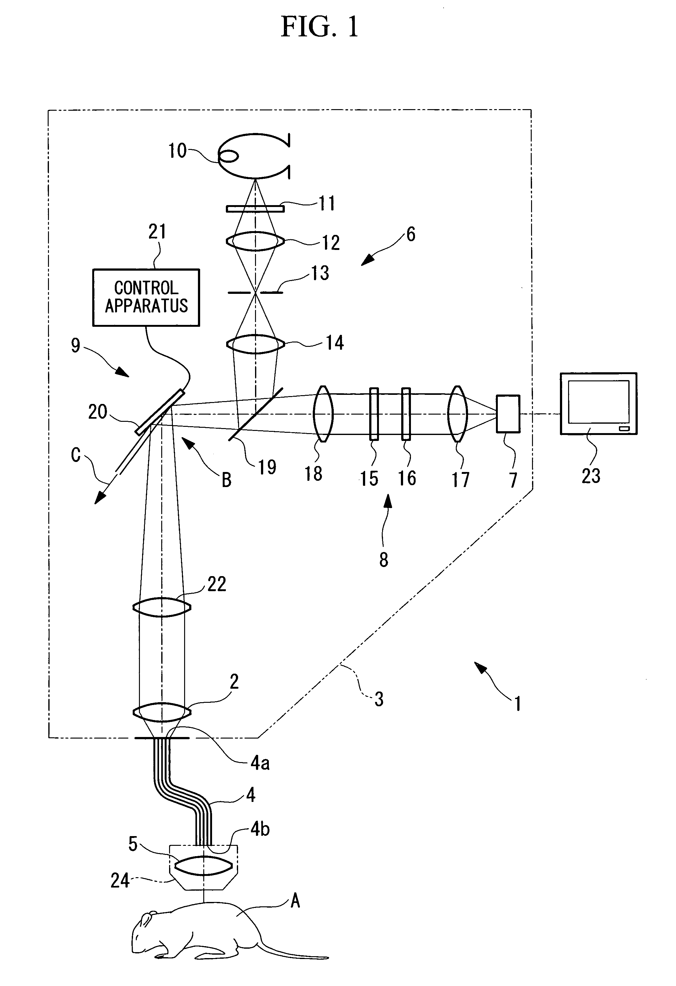
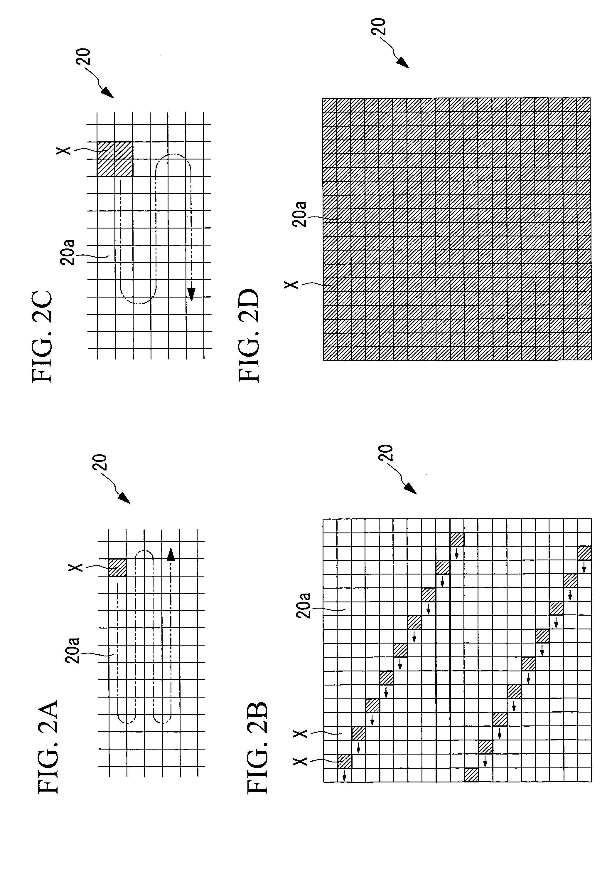
[0040] A description will be given below of an optical-scanning examination apparatus according to an embodiment of the present invention, with reference to FIG. 1 and FIGS. 2A to 2D.

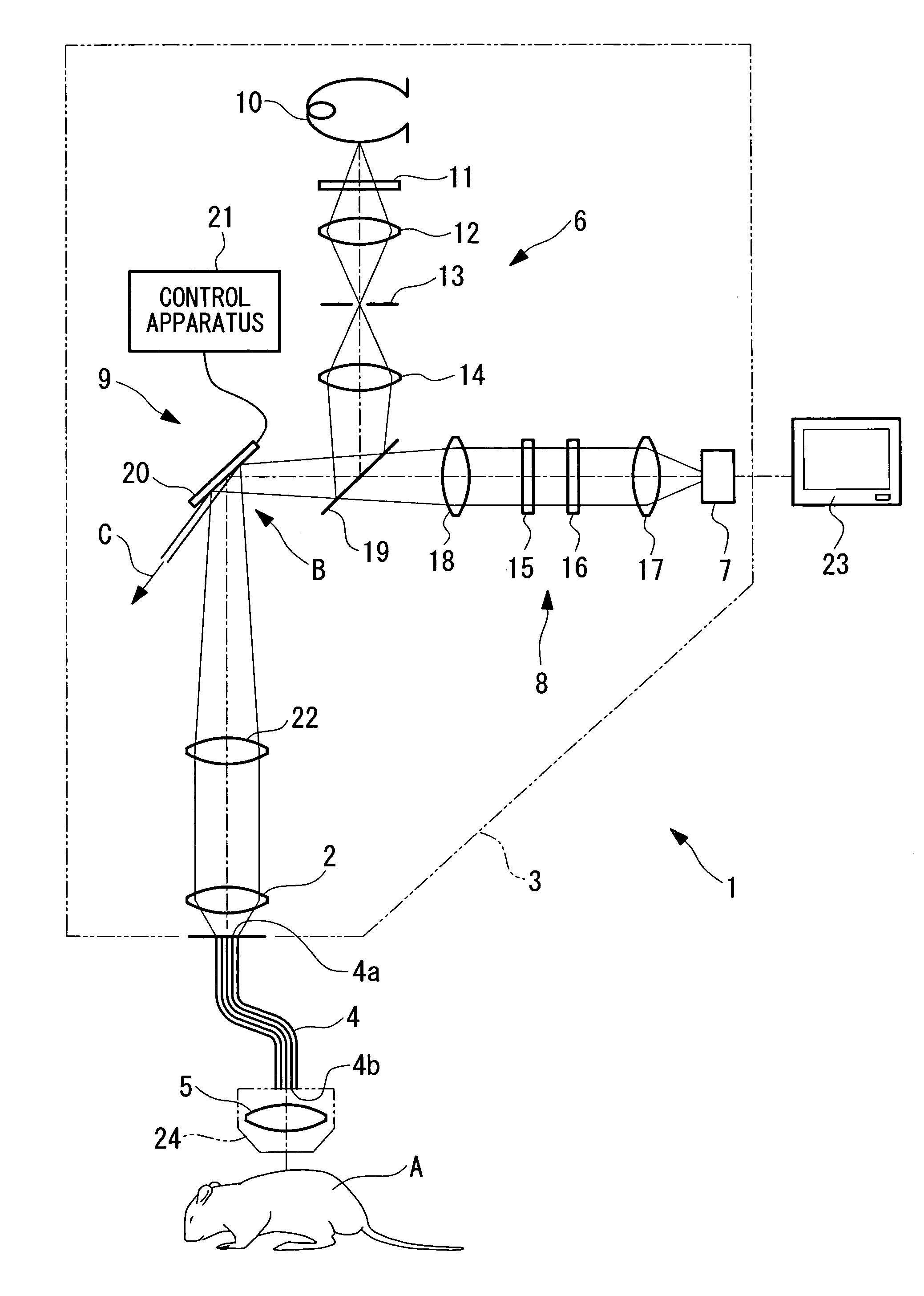
[0041] As shown in FIG. 1, an optical-scanning examination apparatus 1 according to this embodiment includes an apparatus main body 3 provided with a first objective lens 2; an optical fiber bundle 4, one end 4a thereof being disposed at the image position of the first objective lens 2; and a second objective lens 5, which is disposed at another end 4b of the optical fiber bundle 4a and which images light emitted from the other end 4b onto a specimen A.

[0042] A light source unit 6 that emits excitation light, an imaging unit 8 that includes an imaging device 7, such as a photomultiplier, that images return light returning from the specimen A, and an optical scanning unit 9 that two-dimensionally scans the excitation light emitted from the light source unit 6 are provided in the apparatus main body 3. ...

second embodiment

[0068] Next, an optical-scanning examination apparatus 30 according to a second embodiment of the present invention will be described below with reference to FIG. 4.

[0069] In the description of this embodiment, the same reference numerals are assigned to parts having the same configuration as in the optical-scanning examination apparatus according to the first embodiment described above, and a description thereof is omitted.

[0070] The optical-scanning examination apparatus 30 according to this embodiment differs from the optical-scanning examination apparatus according to the first embodiment in that a light source unit 31, including a laser light source 32 and a cylindrical lens 33, produces a band of collimated light, and the structure of an optical scanning unit 34 is different.

[0071] The light source unit 31 includes a collimator lens 35, which converts the laser light emitted by the laser light source 32 into a collimated beam.

[0072] The optical scanning unit 34 includes a ...

third embodiment

[0078] A description of an optical-scanning confocal examination apparatus according to a third embodiment of the present invention will be given below with reference to FIGS. 7 and 8.

[0079] As shown in FIG. 7, an optical-scanning confocal examination apparatus 51 according to this embodiment, which is a laser-scanning confocal microscope, includes an apparatus main body 53 having a first objective lens 52; an optical fiber bundle 54 of which one end 54a is disposed at an image position of the first objective lens 52; and a second objective lens 55, which is disposed at the other end 54b of the optical fiber bundle 54 and which images the light emitted from the other end 54b onto a specimen A.

[0080] The apparatus main body 53 contains laser light sources 56 that generate laser light; an optical scanning unit 57, formed of two galvano mirrors 57a and 57b that can be oscillated around two orthogonal axes, that two-dimensionally scans the laser light emitted from the laser light sour...


PUM


Abstract

The invention provides an optical-scanning examination apparatus with a simple configuration, in which the resolution of acquired images can be freely changed and in which the fluorescence image intensity and examination depth can be adjusted to suit the purpose of examination. The optical-scanning examination apparatus includes a light source unit; a focusing lens for forming a first intermediate image of excitation light; an imaging lens; a first objective lens; an optical fiber bundle; a second objective lens; and an imaging unit for imaging return light that returns via the second objective lens, the optical fiber bundle, the first objective lens, and the imaging lens. In addition, a scanning mirror device, which is disposed at the first intermediate image position, is formed of a plurality of mirrors that simultaneously receive the first intermediate image and that can be selectively turned on and off.

Description

BACKGROUND OF THE INVENTION [0001] 1. Field of the Invention [0002] The present invention relates to an optical-scanning examination apparatus. [0003] 2. Description of Related Art [0004] In the related art, the apparatus disclosed in Japanese Unexamined Patent Application Publication No. 2003-344777 (FIG. 1, etc.) is a known example of this type of optical-scanning examination apparatus. [0005] This optical-scanning examination apparatus includes a scanning laser microscope formed of a fluorescence microscope, an optical fiber bundle one end of which is disposed at the focal plane of a first objective lens in this scanning laser microscope, and a second objective lens disposed so that the other end of this optical fiber bundle serves as a light source therefor. [0006] With this optical-scanning examination apparatus, the end of the optical fiber functions as a confocal pinhole, and fluorescence is produced at the focal position of the second objective lens by the laser light focuse...

Claims


Application Information

Patent Timeline
IPC IPC(8): G02B21/00G02B23/26
CPCG02B21/004G02B21/0076G02B21/0048
Inventor KAWANO, YOSHIHIROHIRATA, TADASHINAKATA, TATSUOTANIKAWA, YOSHIHISA
Owner EVIDENT CORP
Why Eureka
Try Eureka