Optical recording disk device and manufacturing method therefor

a technology of optical recording disk and manufacturing method, which is applied in the direction of recording information storage, disposition/mounting of heads, instruments, etc., can solve the problem of inability to reduce the thickness of optical recording disk devices, and achieve the effect of reducing the thickness of optical recording disk devices, and simplifying the construction of chassis

Inactive Publication Date: 2005-02-03
SANKYO SEIKI MFG CO LTD
View PDF6 Cites 0 Cited by
  • Summary
  • Abstract
  • Description
  • Claims
  • Application Information

AI Technical Summary

Benefits of technology

[0006] In order to achieve the above advantage, according to the present invention, there is provided an optical recording disk device including an optical head mechanism provided with an optical system for converging an emitted light beam from a light source on an optical recording disk, a frame to which the optical head mechanism is mounted, two guide shafts for guiding the frame in a radial direction of the optical recording disk, a disk drive mechanism provided with a turntable for holding the optical recording disk, and a chassis to which the frame, the two guide shafts and the disk drive mechanism are mounted. At least one of the two guide shafts is constructed such that the inclination of the one of the guide shafts is unable to be adjusted and fixed with respect to the chassis in an optical axis direction toward the optical recording disk.
[0007] In accordance with an embodiment of the present invention, an adjusting mechanism of the parallelism between the two guide shafts may be constructed between one of two guide shafts and the chassis, by which the parallelism of one of the guide shafts is adjusted, but an adjusting mechanism is not constructed for the other of the guide shafts to adjust its inclination in an optical axial direction. Also, in accordance with an embodiment of the present invention, no inclination adjustment mechanism may be constructed on both the two guide shafts.
[0008] According to a manufacturing method for an optical recording disk device in accordance with an embodiment of the present invention, two guide shafts for mounting the frame are fixed on the chassis and the disk drive mechanism is mounted to the chassis and then the inclination adjustment of the optical head mechanism is performed with the turntable of the disk drive mechanism as a reference. After that, the optical head mechanism is mounted to the frame. In this case, after the frame is mounted to the two guide shafts, the two guide shafts may be fixed to the chassis, or the frame may be mounted to the two guide shafts after the two guide shafts are fixed to the chassis.
[0009] In accordance with an embodiment of the present invention, the disk drive mechanism is mounted to the chassis and then the inclination adjustment of the optical head mechanism is performed with the turntable of the disk drive mechanism as a reference and then the optical head mechanism is mounted to the frame. Therefore, the inclination of the optical axis of a laser beam emitted from the optical head mechanism is directly adjusted with respect to the optical recording disk which rotates on the turntable and thus, the inclination adjustment of two guide shafts are not required. Accordingly, a wide clearance is not required in order to ensure the displacement of the frame when the inclinations of the two guide shafts are adjusted as with the conventional method. Consequently, the thickness of the optical recording disk device can be reduced. Also, the chassis is not required to be provided with an inclination adjustment mechanism for the two guide shafts in the optical axis direction toward the optical recording disk and thus the construction of the chassis can be simplified.
[0010] According to another manufacturing method for an optical recording disk device in accordance with an embodiment of the present invention, two guide shafts for mounting the frame are fixed on the chassis and the optical head mechanism is mounted to the frame and then the inclination adjustment of the disk drive mechanism is performed with the optical head mechanism as a reference. After that, the disk drive mechanism is mounted to the chassis.
[0011] In accordance with an embodiment of the present invention, the optical head mechanism is mounted to the two guide shafts via the frame and then an inclination adjustment of the disk drive mechanism is performed with the optical head mechanism as a reference and then the disk drive mechanism is mounted to the chassis. Therefore, the inclination of the optical axis of a laser beam emitted from the optical head mechanism is directly adjusted with respect to the optical recording disk which rotates on the turntable and thus, the inclination adjustment of the two guide shafts are not required. Accordingly, a wide clearance is not required in order to ensure the displacement of the frame when the inclinations of the two guide shafts are adjusted as with the conventional method. Consequently, the thickness of the optical recording disk device is reduced. Also, the chassis is not required to be provided with an inclination adjustment mechanism for two guide shafts in the optical axis direction toward the optical recording disk and thus the construction of the chassis can be simplified.

Problems solved by technology

Therefore, in this conventional method, when the inclinations of the two guide shafts are adjusted, the frame supported by the two guide shafts also inclines to a large extent, and thus a wide space for adjustment is required between the frame and a lower cover disposed under the frame, which results in being unable to reduce the thickness of the optical recording disk device.

Method used


Image

  • Optical recording disk device and manufacturing method therefor
  • Optical recording disk device and manufacturing method therefor
  • Optical recording disk device and manufacturing method therefor

Examples


first embodiment

[0042] FIGS. 4(A) through 4(D) are explanatory views showing respective steps to perform the inclination adjustment of the optical head device with the turntable of the disk drive mechanism as a reference in a manufacturing method for the optical recording disk device in accordance with a first embodiment of the present invention.

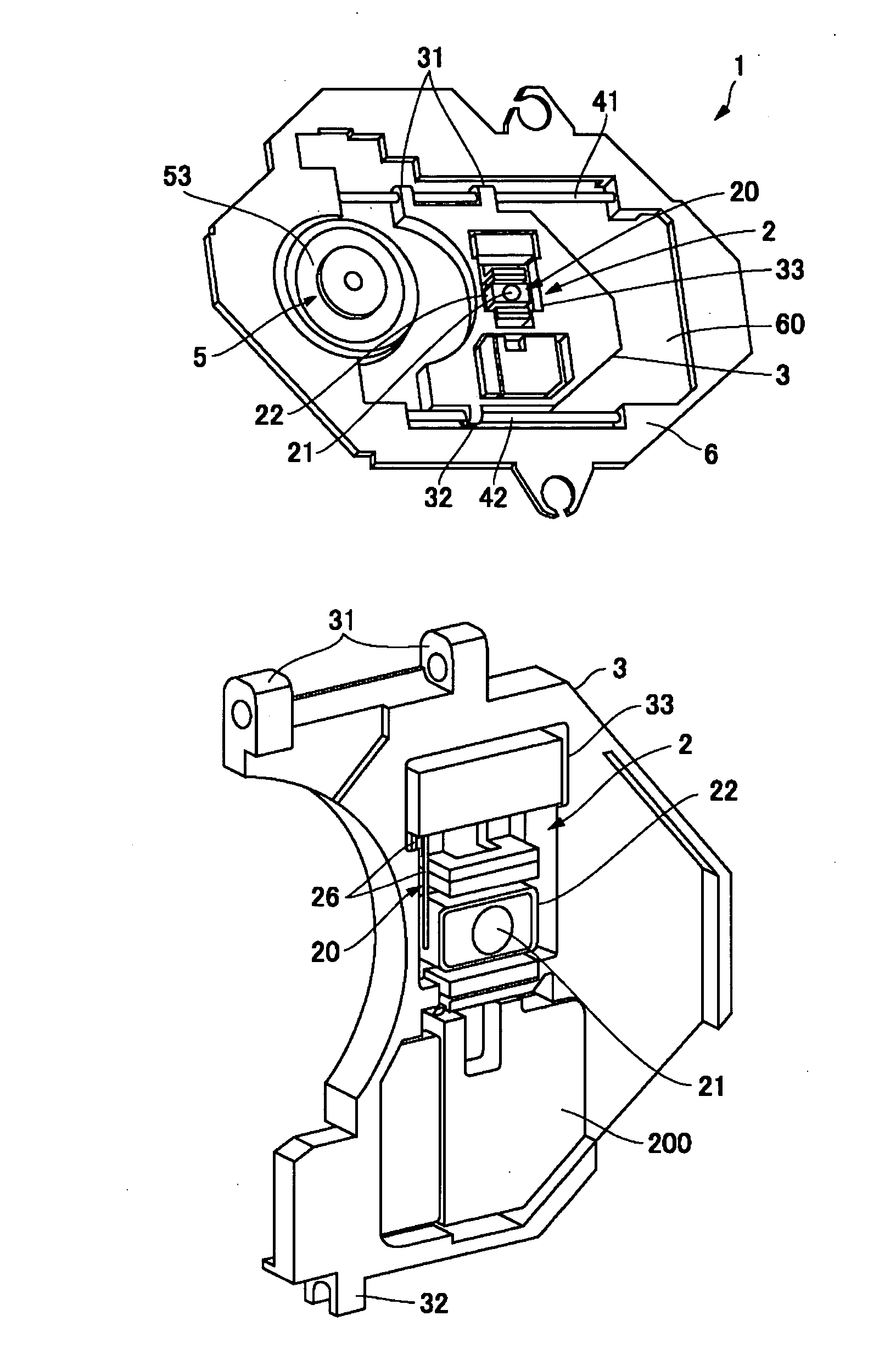
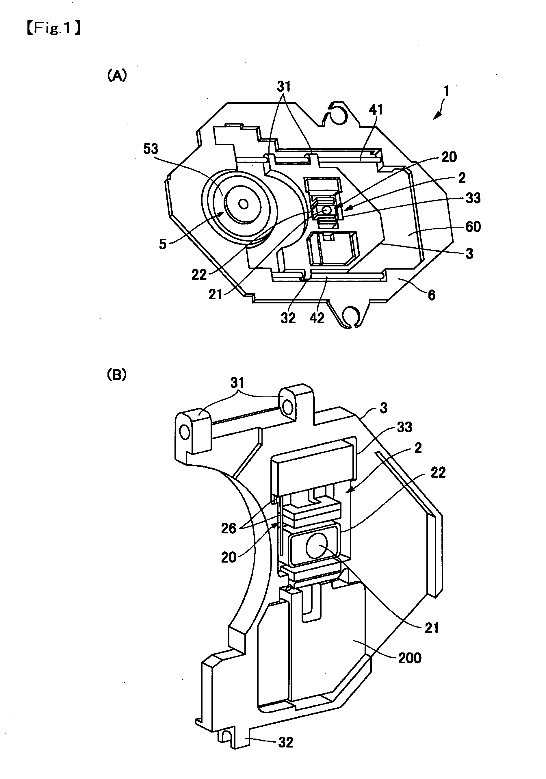
[0043] In FIGS. 1(B) and 2, the optical recording disk device 1 of the first embodiment of the present invention is constructed such that the optical module 200 and the raising mirror of the optical head mechanism 2 are mounted to the frame 3 such that their inclinations are capable of being adjusted. On the other hand, two guide shafts 41, 42 are constructed such that their inclinations are unable to be adjusted with respect to the chassis 6, in other words, the inclinations of two guide shafts 41, 42 are fixed on the chassis 6.

[0044] In order to adjust the inclination of the optical axis of the laser beam with respect to the optical recording disk 7 in ...

second embodiment

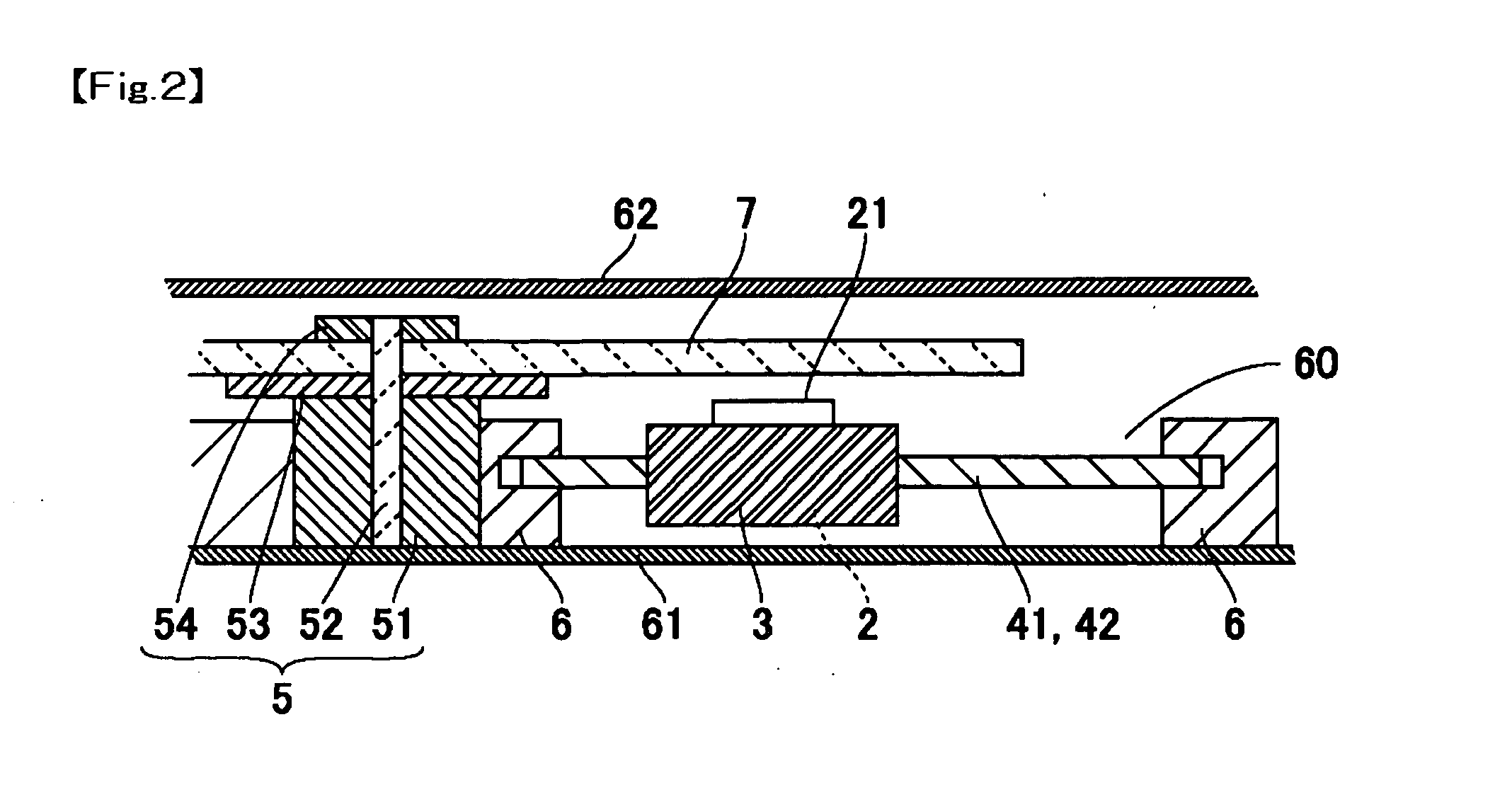
[0051] In FIGS. 1(A) and 2, the optical recording disk device 1 in accordance with the second embodiment of the present invention is constructed such that the disk drive mechanism 5 is mounted on the chassis 6 in the state that the inclination of the disk drive mechanism 5 has been adjusted. Two guide shafts 41, 42 are constructed such that the guide shafts 41, 42 are unable to perform the inclination adjustment with respect to the chassis 6, in other words, the inclinations of the guide shafts 41, 42 are fixed with respect to the chassis 6.

[0052] In order to adjust the inclination of the optical axis of the laser beam with respect to the optical recording disk 7 in the manufacturing method of the optical recording disk device 1, first, the frame 3 is mounted to two guide shafts 41, 42 and the two guide shafts 41, 42 are fixed to the chassis 6. Alternatively, after the two guide shafts 41, 42 are fixed on the chassis 6, the frame 3 may be mounted on the two guide shafts 41, 42.

[00...

third embodiment

[0056] In FIGS. 1(A) and 2, the optical recording disk device 1 in accordance with the third embodiment of the present invention is constructed such that the optical head mechanism 2 is mounted on the frame 3 in the state that the inclination of the optical head mechanism 2 has been adjusted and the disk drive mechanism 5 is mounted on the chassis 6 in the state that the inclination of the disk drive mechanism 5 has been adjusted. Two guide shafts 41, 42 are constructed such that the guide shafts 41, 42 are unable to perform the inclination adjustment with respect to the chassis 6, in other words, the inclinations of the guide shafts 41, 42 are fixed with respect to the chassis 6.

[0057] In order to adjust the inclination of the optical axis of the laser beam with respect to the optical recording disk 7 in the manufacturing method of the optical recording disk device 1, first, the frame 3 is mounted on two guide shafts 41, 42 and the two guide shafts 41, 42 are fixed on the chassis ...


PUM

PropertyMeasurementUnit
wavelengthaaaaaaaaaa
thicknessaaaaaaaaaa

Abstract

An optical recording disk device includes an optical head mechanism provided with an optical system for converging an emitted light beam from a light source on an optical recording disk, a frame to which the optical head mechanism is mounted, two guide shafts for guiding the frame in a radial direction of the optical recording disk, a disk drive mechanism provided with a turntable for holding the optical recording disk and a chassis to which the frame, the two guide shafts and the disk drive mechanism are mounted. At least one of the two guide shafts is constructed such that the inclination of one of the two guide shafts is unable to be adjusted and fixed with respect to the chassis in an optical axis direction toward the optical recording disk.

Description

FIELD OF THE INVENTION [0001] The present invention relates to an optical recording disk device that is used for reproduction or the like of an optical recording disk such as a CD or a DVD and relates to a manufacturing method for the optical recording disk device. BACKGROUND OF THE INVENTION [0002] An optical recording disk device which is used for recording onto or reproducing from an optical record disk such as a CD or a DVD includes an optical head mechanism provided with an optical system for converging an emitted light beam from a light source into an optical recording disk, a frame on which the optical head mechanism is mounted, two guide shafts for guiding the frame in the radial direction of the optical record disk, a disk drive mechanism provided with a turntable on which the optical record disk is held, and a chassis to which the frame, the two guide shafts and the disk drive are mounted. [0003] In the optical recording disk drive, the laser beam that is emitted from the ...

Claims


Application Information

Patent Timeline
Patent Type & Authority Applications(United States)
IPC IPC(8): G11B7/08G11B7/00G11B7/085G11B7/09G11B7/135G11B7/22G11B7/26
CPCG11B7/08582
Inventor WADE, TATSUKI
Owner SANKYO SEIKI MFG CO LTD
Why Eureka
Try Eureka