Near-eye optical system

a technology of optical system and optical waveguide, which is applied in the field of optical system, can solve the problems of reducing affecting the appearance of the mirror, so as to reduce the thickness of the optical waveguide and alleviate the problem

Active Publication Date: 2021-05-13
CORETRONIC
View PDF2 Cites 1 Cited by
  • Summary
  • Abstract
  • Description
  • Claims
  • Application Information

AI Technical Summary

Benefits of technology

[0008]The invention provides a near-eye optical system further reducing a thickness of an optical waveguide and alleviating an issue that an image beam is not completely projected to the optical waveguide.

Problems solved by technology

In an optical lens of the projection device, in order to achieve the object of a large field of view (FOV) and a small volume, many difficulties are encountered in the design.
However, due to the reduction of pupil aperture, the expansion in an optical waveguide is more difficult.
When the thickness of the projection device is limited by the system length of the optical lens, designers usually may only reduce the thickness of the optical waveguide.
However, reducing the thickness of the optical waveguide also reduces the optical coupling range of the optical waveguide.
Therefore, an image beam emitted by the projection device may not be completely projected to the optical coupling region of the optical waveguide, and therefore, the thickness of the optical waveguide is still not readily reduced.
Furthermore, the increase in the thickness of the optical waveguide reduces the number of total reflections of the image beam in the optical waveguide, so that an angle information transmitted by the image beam to a projection target may be discontinuous, and the situation in which the overall image lacks light or has dark streaks occurs.
Such a situation is more serious particularly when the pupil aperture of the optical lens is reduced, so that user experience is poor.

Method used


Image

  • Near-eye optical system
  • Near-eye optical system
  • Near-eye optical system

Examples


Embodiment Construction

[0024]In the following detailed description of the preferred embodiments, reference is made to the accompanying drawings which form a part hereof, and in which are shown by way of illustration specific embodiments in which the invention may be practiced. In this regard, directional terminology, such as “top,”“bottom,”“front,”“back,” etc., is used with reference to the orientation of the Figure(s) being described. The components of the present invention may be positioned in a number of different orientations. As such, the directional terminology is used for purposes of illustration and is in no way limiting. On the other hand, the drawings are only schematic and the sizes of components may be exaggerated for clarity. It is to be understood that other embodiments may be utilized and structural changes may be made without departing from the scope of the present invention. Also, it is to be understood that the phraseology and terminology used herein are for the purpose of description an...


PUM

PropertyMeasurementUnit
angleaaaaaaaaaa
reflectancesaaaaaaaaaa
convex microstructuresaaaaaaaaaa

Abstract

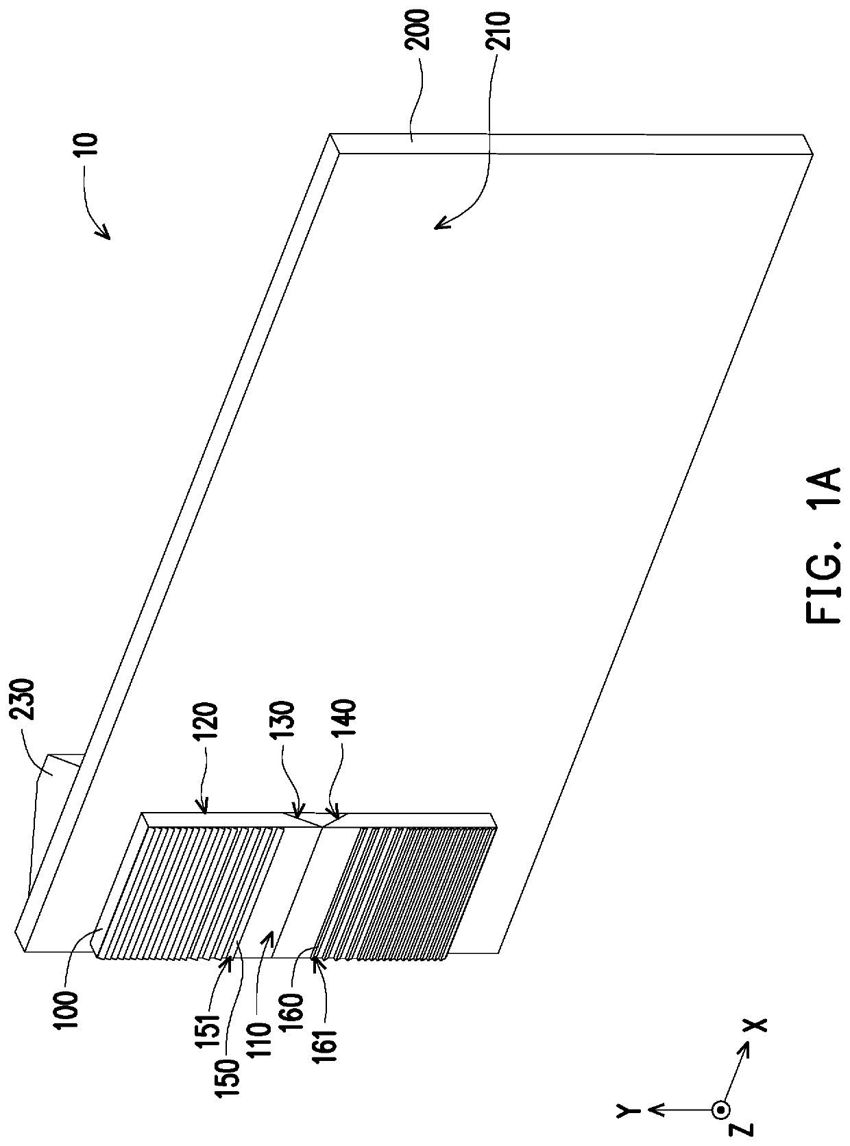
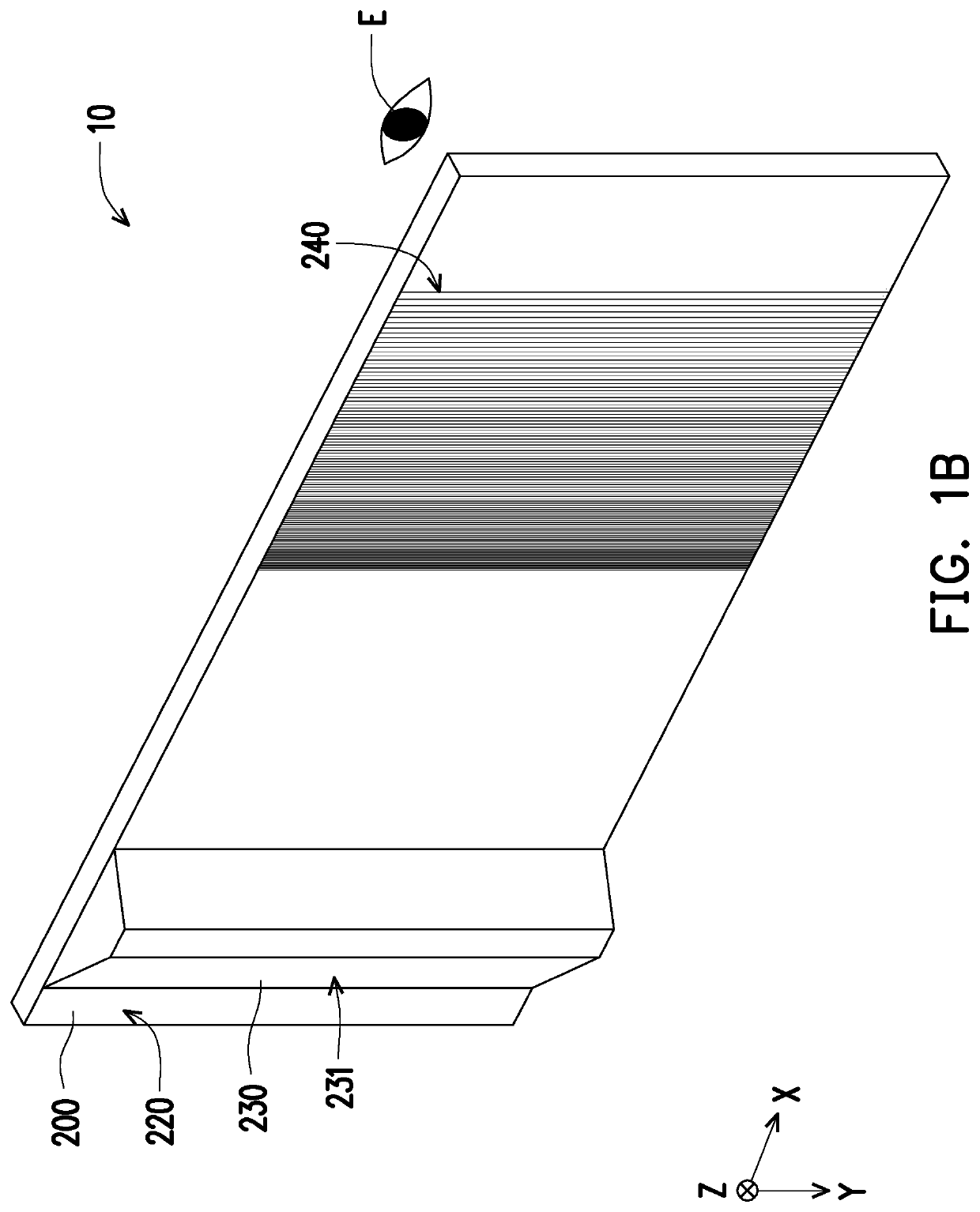
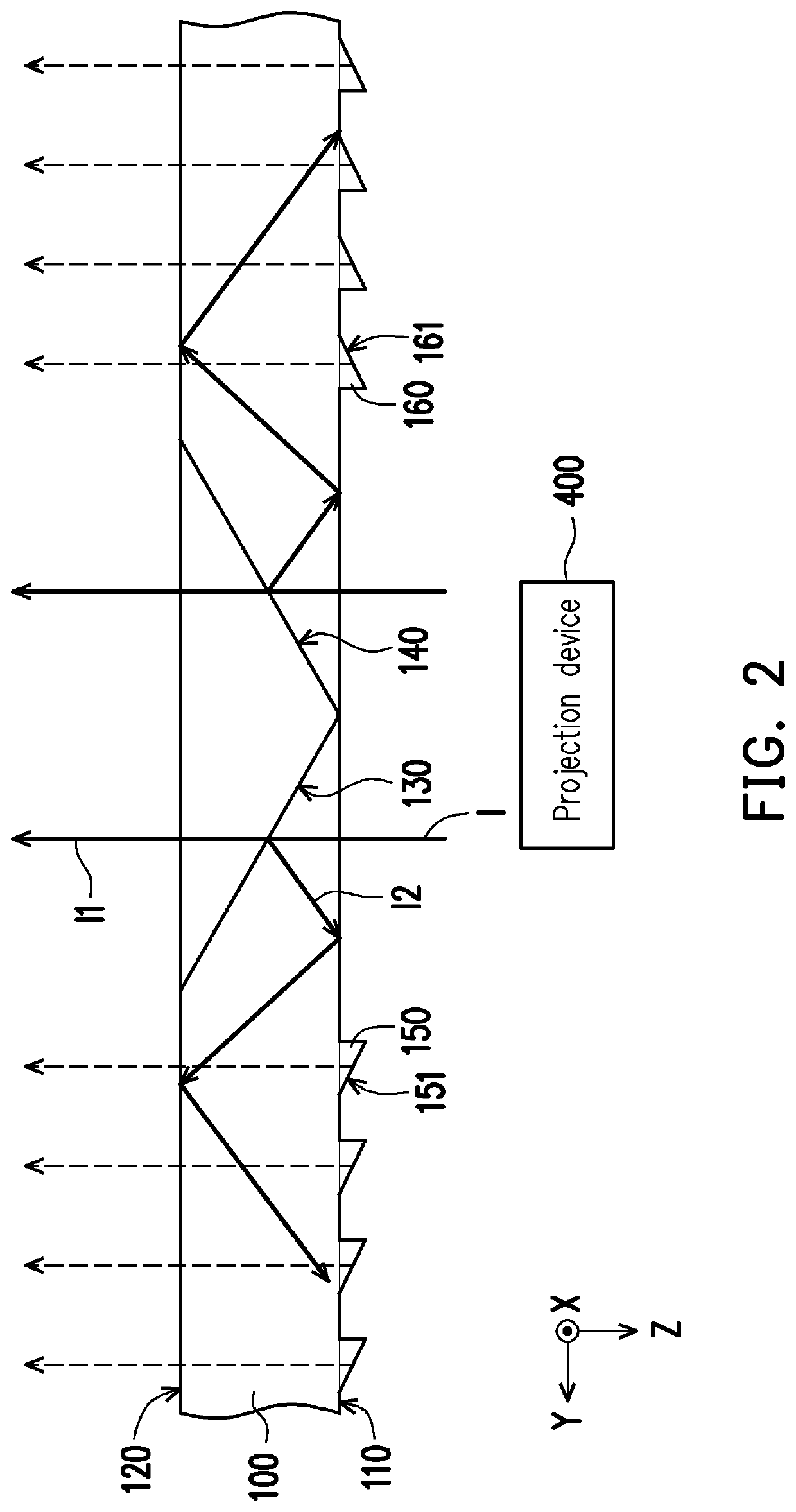
A near-eye optical system receiving an image beam including a first optical waveguide is provided. The first optical waveguide expands the image beam in a first direction and includes first and second surfaces, first and second beam-splitting surfaces, and a plurality of first and second reflective inclined surfaces. The first and second beam-splitting surfaces are located in the first optical waveguide and disposed in a tilted manner relative to the first and second surfaces. The first and second beam-splitting surfaces have opposite tilt directions. The first and second beam-splitting surfaces receive an image beam incident from the first surface so that a first portion of the image beam passes through and a second portion of the image beam is reflected. The near-eye optical system further reduces a thickness of the optical waveguide and alleviates the issue that the image beam is not completely projected to the optical waveguide.

Description

CROSS-REFERENCE TO RELATED APPLICATION[0001]This application claims the priority benefit of U.S. provisional applications Ser. No. 62 / 931,811, filed on Nov. 7, 2019 and China application serial no. 202020138586.9, filed on Jan. 21, 2020. The entirety of the above-mentioned patent application is hereby incorporated by reference herein and made a part of this specification.BACKGROUND OF THE INVENTIONField of the Invention[0002]The invention relates to an optical system, and in particular to a near-eye optical system.Description of Related Art[0003]The history of near-eye optical systems such as head / helmet-mounted displays (HMDs) may be traced back to the US military in the 1970s. A projection device is used to project images or text message on a display unit into the eyes of a user.[0004]In recent years, with the development of micro display components: the growing trend of higher resolution, smaller size, and lower power consumption, and the development of cloud technology: a large ...

Claims


Application Information

Patent Timeline
Patent Type & Authority Applications(United States)
IPC IPC(8): G02B27/01F21V8/00
CPCG02B27/0176G02B27/0172G02B2027/015G02B6/0016G02B6/0075G02B6/0023G02B27/0081G02B27/106G02B5/09G02B2027/0121G02B2027/0123
Inventor SHIH, CHIH-WEI
Owner CORETRONIC
Why Eureka
Try Eureka