Optical cavity with strong dynamic

a cavity and optical technology, applied in the field of optical cavities, can solve the problems of insufficient extent of the detectable concentration area of the cavity of the prior art, and achieve the effects of reducing the thickness increasing the compactness of the optical cavity, and achieving the same optical efficiency

Active Publication Date: 2019-01-24
COMMISSARIAT A LENERGIE ATOMIQUE ET AUX ENERGIES ALTERNATIVES
View PDF0 Cites 0 Cited by
  • Summary
  • Abstract
  • Description
  • Claims
  • Application Information

AI Technical Summary

Benefits of technology

[0046]making it possible to reduce the thickness of the optical cavity (gain in compactness) compared to the prior art for a same optical efficiency.
[0047]Yet, an optical cavity of the prior art makes it possible to obtain a compact sensor in the plane of the optical cavity, but not in the thickness of the optical cavity. Indeed, the thickness of the optical cavity is imposed by the thickness of the light source. A reduction in the thickness of the optical cavity leads to a reduction in the size of the light source, and simultaneously to a loss of optical efficiency. A possibility for compensation would be to increase the power of the light source, at the expense of the electrical consumption.

Problems solved by technology

Such a cavity of the prior art is not entirely satisfactory in terms of extent of the detectable concentration area.

Method used


Image

  • Optical cavity with strong dynamic
  • Optical cavity with strong dynamic

Examples


embodiment example

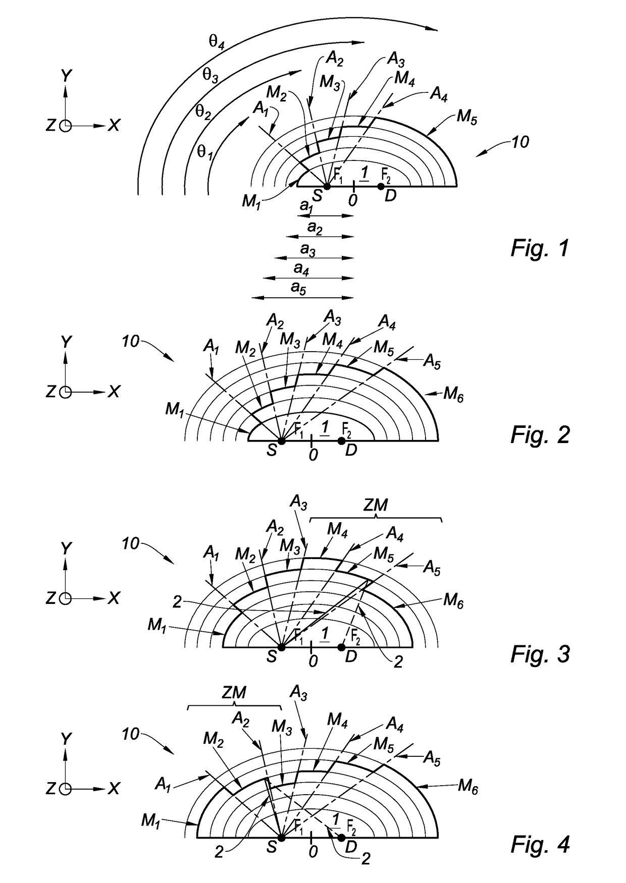
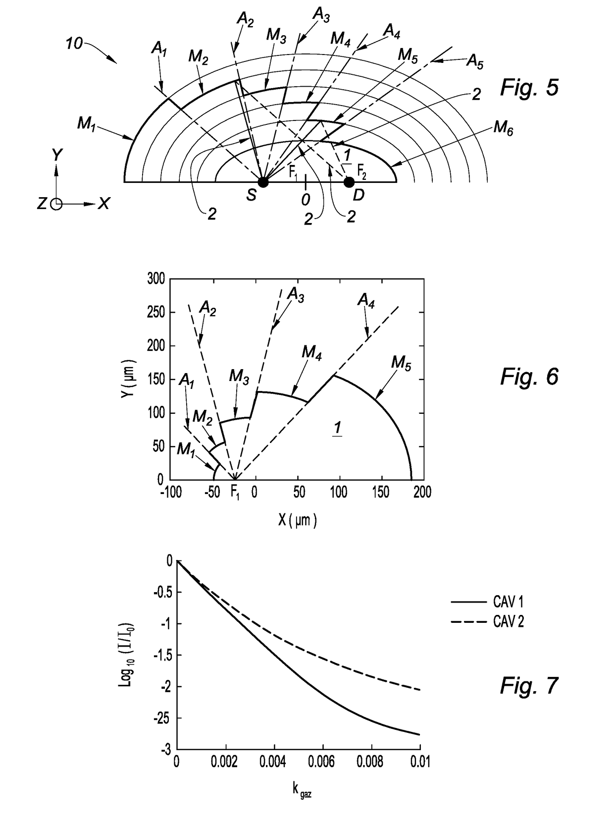
[0080]In the example illustrated in FIG. 6, the set of elliptical mirrors includes five elliptical mirrors M1 to M5 (N=5). The elliptical mirrors M1 to M5 are arranged consecutively from the first common focal point F1 toward the second common focal point F2 such that the consecutive semi-major axes form a strictly increasing geometric sequence, satisfying:

an+1=q an

[0081]where:[0082]n is a natural number between 1 and N−1, namely a natural number between 1 and 4,[0083]the semi-major axis of the elliptical mirror M1 satisfies: A1=50 μm,[0084]q is the ratio of the geometric sequence satisfying: q=G log(G), with G=2.

[0085]FDTD (“Finite Difference Time Domain”) simulations have been carried out with a wavelength (denoted A) of the light radiation 2 equal to 4.5 μm. The optical cavity 1 is immersed in a fictitious medium, representing a gas, the refractive index real part of which is equal to 1, and the refractive index imaginary part of which is denoted kgaz and satisfies:

kgaz=λ4παC

[00...


PUM

PropertyMeasurementUnit
wavelengthaaaaaaaaaa
angleaaaaaaaaaa

Abstract

This optical cavity (1), includes:
    • a set of elliptical mirrors (M1 to M5), which are intended to receive light radiation emitted by a light source (S), the light radiation leaving the elliptical mirrors (M1 to M5) being intended to be received by a detector (D);
    • a first common focal point (F1) and a second common focal point (F2), which are shared by the set of the elliptical mirrors (M1 to M5), the light source (S) being intended to be arranged at the first common focal point (F1), the detector (D) being intended to be arranged at the second common focal point (F2);
    • a contour, comprising a part formed by the set of the elliptical mirrors (M1 to M5) which are arranged consecutively.

Description

TECHNICAL FIELD[0001]The invention relates to the technical field of optical cavities. The invention is particularly used in spectroscopic sensors. A spectroscopic sensor includes an optical cavity, a light source emitting light radiation, and a detector for the light radiation. The light source can be, for example, a thermal source or a quantum cascade laser. Possible uses are fluid sensors, particle sensors, biosensors, etc.[0002]More precisely, it is possible to mention a nondispersive infrared (conventionally referred to as NDIR) sensor for detecting a fluid such as a gas. The infrared light source is preferentially a thermal source. “Infrared” means a wavelength between 0.78 μm and 12 μm. The infrared detector can be, for example, a bolometer or a pyrometer. The use preferentially envisaged is the detection of a gas, for example CO2, in a reliable manner in an industrial environment, the detection conventionally being a threshold detection. Another possible use is the analysis ...

Claims


Application Information

Patent Timeline
Patent Type & Authority Applications(United States)
IPC IPC(8): G01N21/03G01N21/3504G01N21/05
CPCG01N21/0303G01N21/3504G01N21/05G01N21/01
Inventor BOUTAMI, SALIM
Owner COMMISSARIAT A LENERGIE ATOMIQUE ET AUX ENERGIES ALTERNATIVES
Why Eureka
Try Eureka