Optical element and wafer level optical module
- Summary
- Abstract
- Description
- Claims
- Application Information
AI Technical Summary
Benefits of technology
Problems solved by technology
Method used
Image
Examples
first embodiment
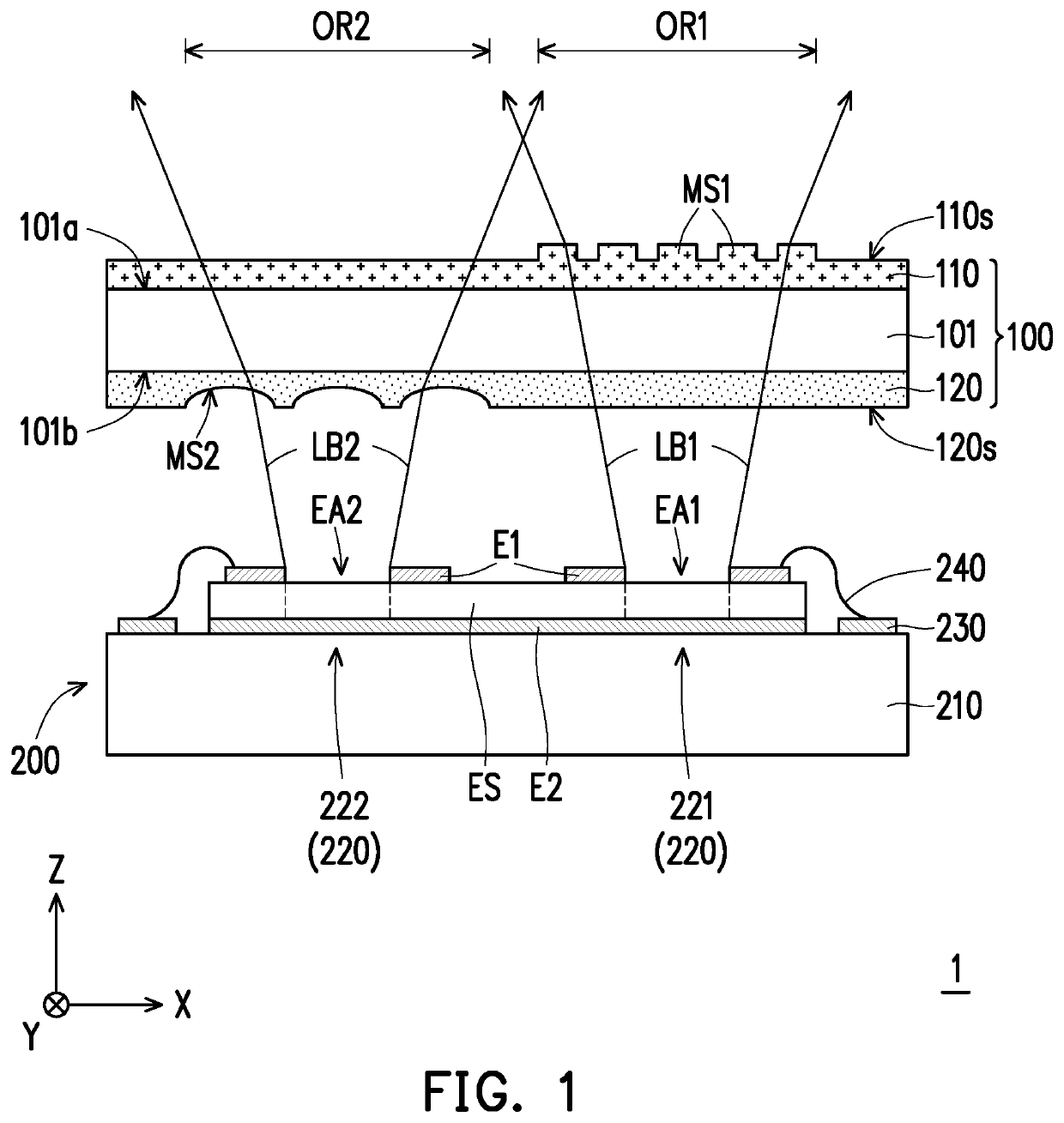
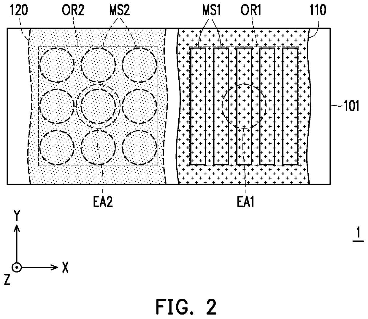
[0039]FIG. 1 is a schematic cross-sectional view of a wafer level optical module according to the invention. FIG. 2 is a schematic top view of the wafer level optical module in FIG. 1. In particular, for clear presentation and explanation, FIG. 2 omits the illustration of first electrode E1, second electrode E2, epitaxial structure ES, circuit substrate 210, pad 230 and bonding wire 240 of FIG. 1.
[0040]Referring to FIG. 1 and FIG. 2, a wafer level optical module includes an optical element 100 and a light emitter 200. The optical element 100 is arranged on the optical path of the light emitter 200. Specifically, the light emitter 200 has a plurality of light exiting apertures, for example, a light exiting aperture EA1 and a light exiting aperture EA2. The optical element 100 is overlapped with these light exiting apertures. For example, in the present embodiment, the optical element 100 has a first optical region OR1 and a second optical region OR2. It should be noted that the first...
second embodiment
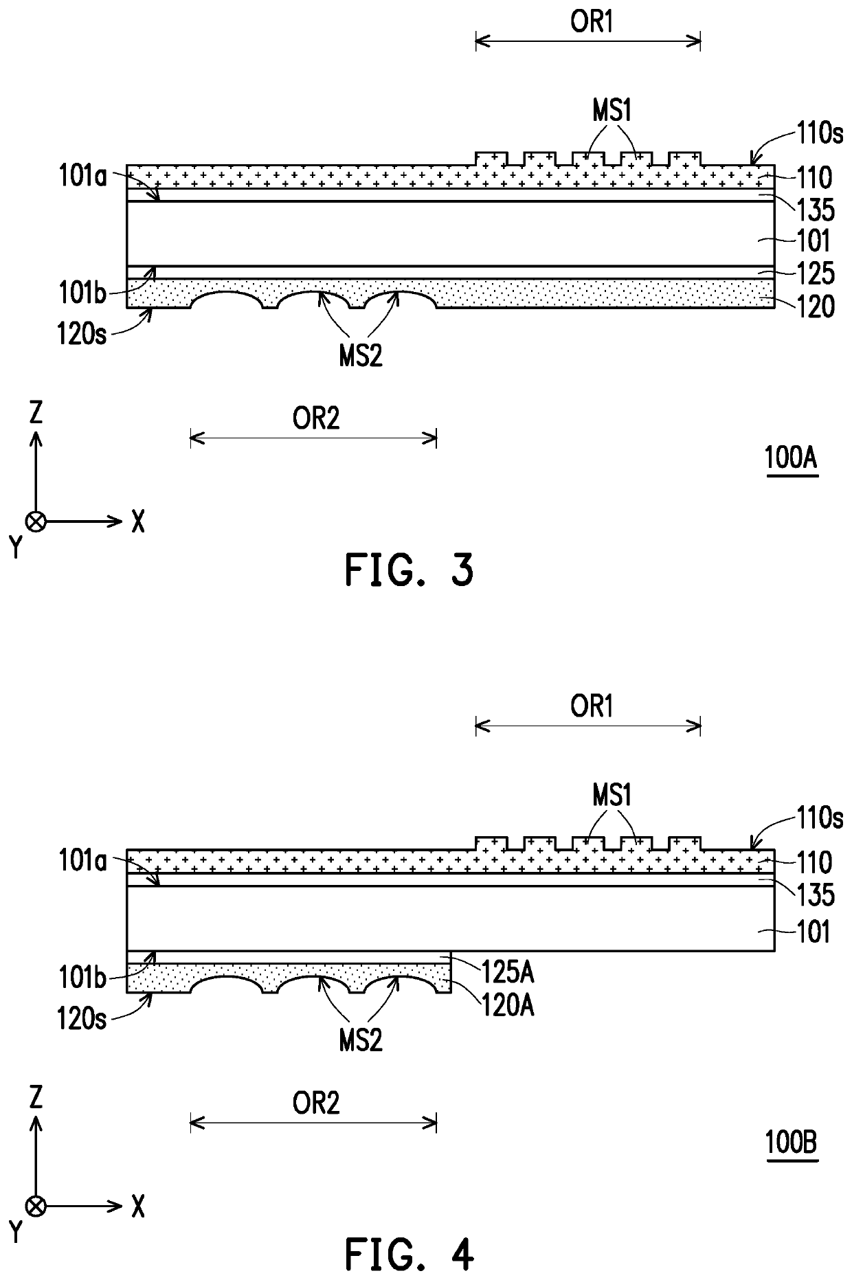
[0053]FIG. 3 is a schematic cross-sectional view of an optical element according to the invention.
[0054]Referring to FIG. 3, the difference between the optical element 100A of the present embodiment and the optical element 100 of FIG. 1 lies in the composition of the optical element. In the present embodiment, the optical element 100A further includes an index matching layer 135 and a buffer layer 125. The index matching layer 135 is disposed between the substrate 101 and the first optical film 110. The buffer layer 125 is disposed between the substrate 101 and the second optical film 120. Due to the refractive index of the first optical film 110 is high (for example, the refractive index is greater than 1.7), the reflection of the light beam at the interface between the substrate 101 and the first optical film 110 can be inhibited by configuring the index matching layer 135. In the present embodiment, the width of the first optical microstructure MS1 or the pitch between adjacent f...
fifth embodiment
[0060]FIG. 6 is a schematic cross-sectional view of an optical element according to the invention.
[0061]Referring to FIG. 6, the difference between the optical element 100D of the present embodiment and the optical element 100 of FIG. 1 lies in the configuration of the optical element. In the present embodiment, the first optical film 110 and the second optical film 120B are located on the same side (for example, the side 101a) of the substrate 101. The first optical film 110 is positioned between the substrate 101 and the second optical film 120B. In addition, due to the refractive index of the first optical film 110 is high (for example, the refractive index is greater than 1.7), the reflection of the light beam at the interface between the substrate 101 and the first optical film 110 can be inhibited by configuring an index matching layer 135. The index matching layer 135 is positioned between the substrate 101 and the first optical film 110.
PUM
 Abstract
Description
Claims
Application Information
 - R&D
- Intellectual Property
- Life Sciences
- Materials
- Tech Scout
- Unparalleled Data Quality
- Higher Quality Content
- 60% Fewer Hallucinations
Browse by: Latest US Patents, China's latest patents, Technical Efficacy Thesaurus, Application Domain, Technology Topic, Popular Technical Reports.
© 2025 PatSnap. All rights reserved.Legal|Privacy policy|Modern Slavery Act Transparency Statement|Sitemap|About US| Contact US: help@patsnap.com


