
Addressable outlet, and a network using same

a technology applied in the field of addressable outlets and network connections, can solve the problems of complex procedures, labor-intensive, time-consuming, and expensive, and achieve the effect of simple testing of the continuity of wiring from the hub to the outlet, and avoiding the installation of new wiring infrastructure in existing buildings

Inactive Publication Date: 2005-02-03
CONVERSANT INTPROP MANAGEMENT INC
View PDF99 Cites 52 Cited by
  • Summary
  • Abstract
  • Description
  • Claims
  • Application Information

AI Technical Summary

Benefits of technology

[0034] It is a further object of the present invention to allow convenient determination of the condition of devices and apparatus connected to the various outlets of an installed wiring system. It is moreover an object of the present invention to permit such determination remotely.
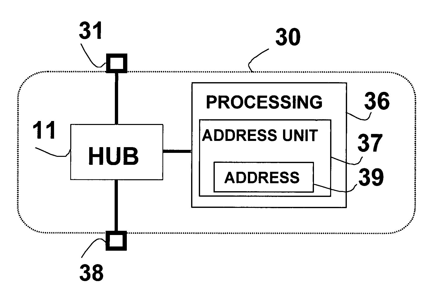
[0035] In order to attain these objectives, the present invention provides an outlet having an address which uniquely identifies the outlet within an information network that is established, at least in part, over wiring to which the outlet is connected. Associated with this unique network address is processing circuitry and an addressing unit capable of storing and utilizing the unique network address, to allow the outlet to receive and send messages associated with the address. The processing circuitry interfaces with the network to support such messaging, and may generate content for messages to be sent to other devices on the network, and may likewise receive and process messages sent to the outlet from other devices. The unique network address is associated with both the sending and receiving of messages over the network. In the case of receiving messages, the unique address allows the circuitry in the outlet to discriminate between messages intended for that outlet and messages intended for other devices. In the case of sending messages, the unique address serves to identify the source of the message. Because addresses are associated both with senders and receivers, the processing circuitry may respond to messages sent to the outlet from other devices by sending messages from the outlet to other devices.

Problems solved by technology

Troubleshooting such failures requires disconnecting cables and inserting dedicated test equipment or making elaborate and thorough substitutions of components that are known to be functional.
Such procedures are complicated, labor-intensive, time-consuming, and expensive.
Furthermore, in the common case of an outlet to which no data unit is connected, there is no simple way to test the continuity of wiring from the hub to the outlet.
In addition, in many cases it is necessary to test the LAN from a remote place (such as via the Internet) in cases where it is not possible to attach testing equipment to non-connected outlets.
However, implementing such a network in existing buildings typically requires installation of new wiring infrastructure.
Such installation of new wiring may be impractical, expensive and hassle-oriented.
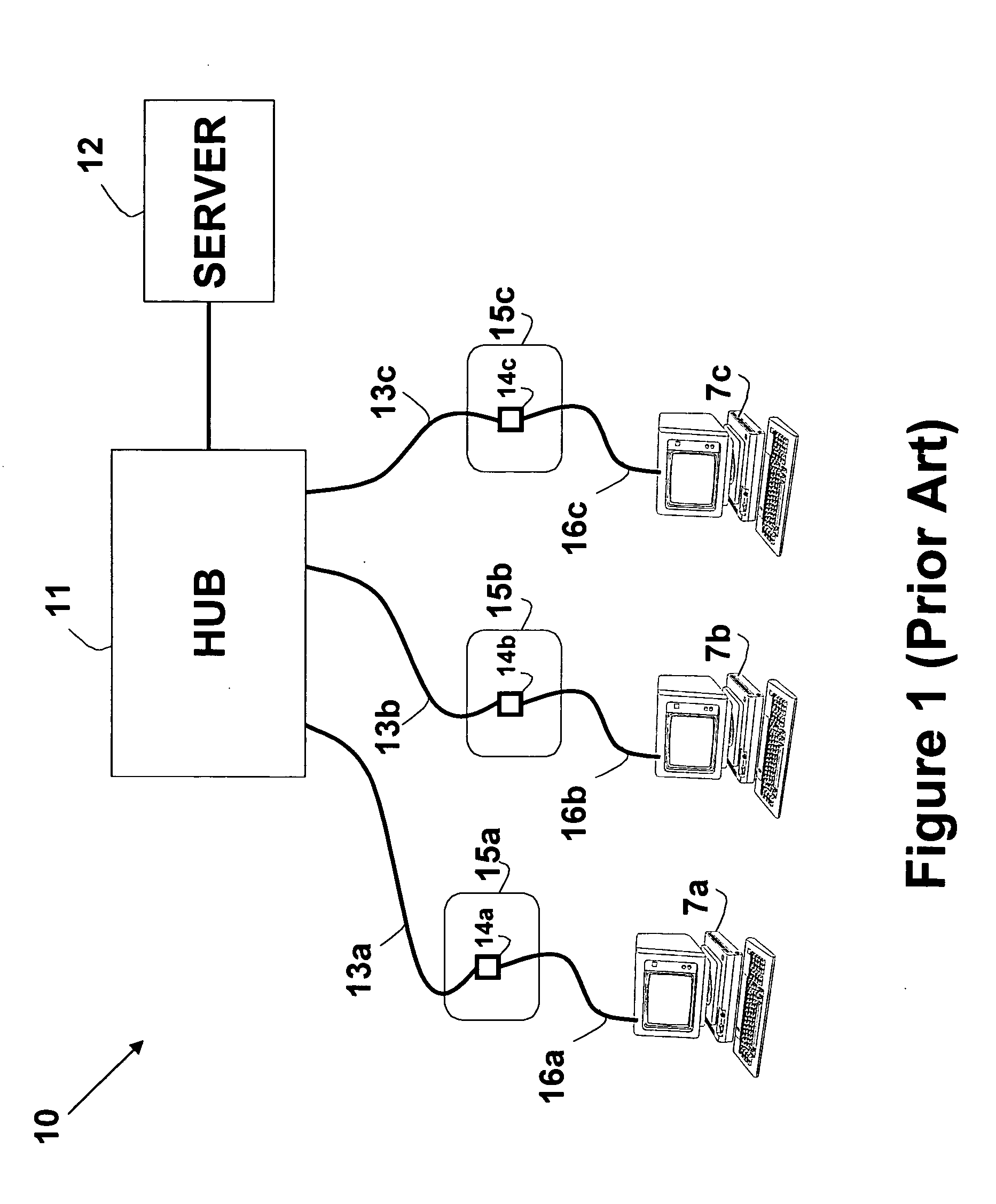
Similarly, a break in the wiring cannot be easily or remotely isolated to wiring 16a or wiring 16b.
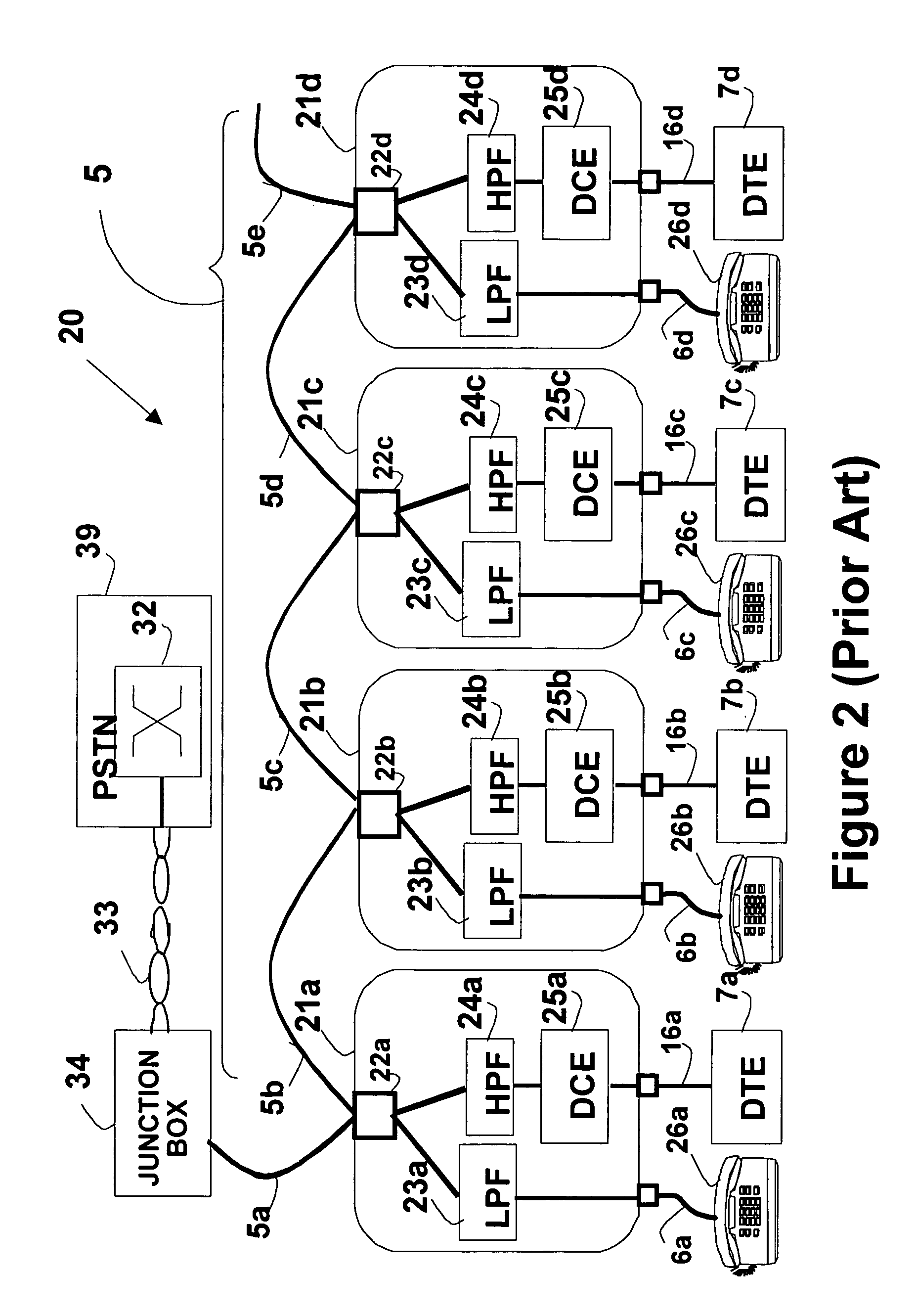
If the failure, however, is in wiring 5c, more troubleshooting will be necessary, and can ultimately involve disconnecting the entire network.
As noted above, this is a complicated, expensive, labor-intensive, and time-consuming effort.
Furthermore, in the common case of an outlet into which no data units are connected, there is no simple way to test wiring continuity to the outlet.
In addition, as explained in WO 99 / 03255 to Bell, in many cases it is required to test the LAN from a remote place (e.g. via the Internet), and no local presence is available to approach the disconnected outlets for attaching testers.
A faulty bus is disconnected if a fault is discovered during monitoring intervals.
In both above prior art patents, passive outlets are used, hence there is no way to distinguish between a failure in the wiring into which the outlets are connected, and a failure in the wiring / equipment connected to the outlet.

Method used


Image

  • Addressable outlet, and a network using same
  • Addressable outlet, and a network using same
  • Addressable outlet, and a network using same

Examples


Embodiment Construction

[0049] The principles and operation of a network according to the present invention may be understood with reference to the drawings and the accompanying description. The drawings and descriptions are conceptual only. In actual practice, a single component can implement one or more functions; alternatively, each function can be implemented by a plurality of components and circuits. In the drawings and descriptions, identical reference numerals indicate those components that are common to different embodiments or configurations.

[0050]FIG. 3 schematically shows an outlet 30 according to a first embodiment of the invention. As shown in FIG. 3, outlet 30 includes a three-port hub 11. One port goes to a connector 31, which connects the outlet 30 to network wiring as previously described, and as is known in the art (such as to wiring 13a in FIG. 1). Another hub port goes to a connector 38, enabling connection of a data unit as described previously and as is known in the art (such as to d...


PUM


Abstract

An addressable outlet for use as part of local area network based on wiring installed in a building, such as telephone, electrical, cable television, dedicated wiring, and the like. The use of such wiring for data communications networks in addition to the wiring's primary usage creates a need for ways of determining the condition of the network and monitoring this information remotely. Network condition includes such factors as continuity of wiring, connector status, connected devices, topology, signal delays, latencies, and routing patterns. Providing basic processing and addressing capabilities within the outlet permits messaging to and from specific individual outlets, thereby allowing inquiries and reports of the condition of the immediate environment of each outlet. In addition, outlets can be configured with sensors to report on voltage, temperature, and other measurable quantities.

Description

FIELD OF THE INVENTION [0001] The present invention relates to the field of wired Local Area Networks (LAN's) using outlets, and, more specifically, to an addressable outlet for use in such networks. BACKGROUND OF THE INVENTION [0002] Outlets [0003] The term “outlet” herein denotes an electromechanical device, which facilitates easy, rapid connection and disconnection of external devices to and from wiring installed within a building. An outlet commonly has a fixed connection to the wiring, and permits the easy connection of external devices as desired, commonly by means of an integrated connector in a faceplate. The outlet is normally mechanically attached to, or mounted in, a wall. Non-limiting examples of common outlets include: telephone outlets for connecting telephones and related devices; CATV outlets for connecting television sets, VCR's, and the like; and electrical outlets for connecting power to electrical appliances. The term “wall” herein denotes any interior or exterio...

Claims


Application Information

Patent Timeline
Patent Type & Authority Applications(United States)
IPC IPC(8): H04L12/24H04L12/26H04L12/28H04L12/44
CPCH04L12/2803H04L12/2818H04L12/2827H04L12/44H04L2012/2845H04L41/0677H04L61/6022H04L2012/2843H04L29/12839H04L2101/622
Inventor BINDER, YEHUDA
Owner CONVERSANT INTPROP MANAGEMENT INC
Learn More