

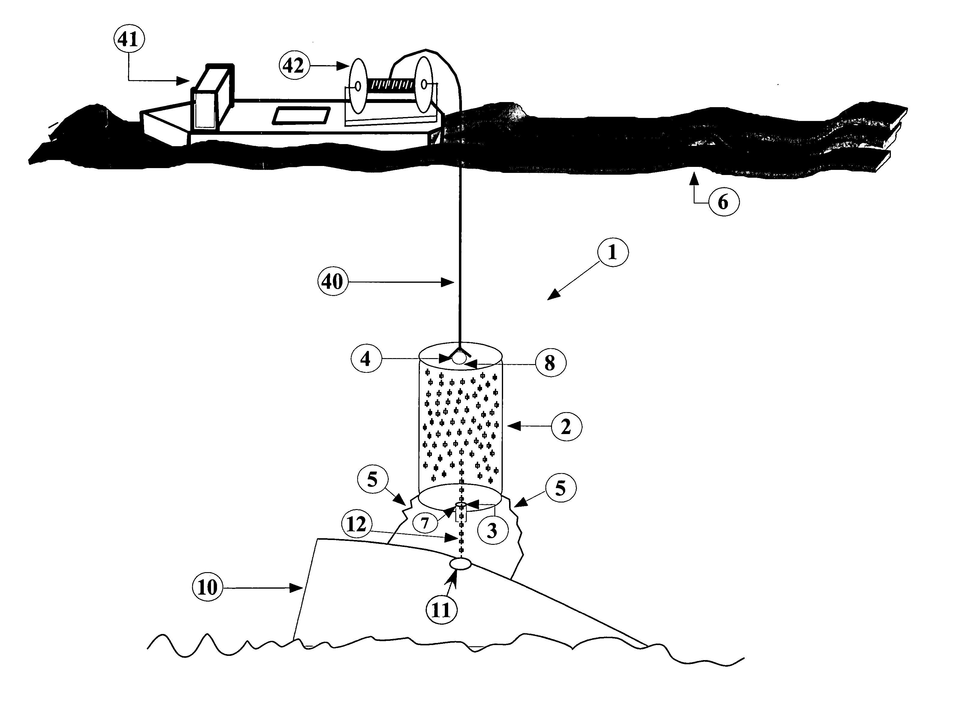
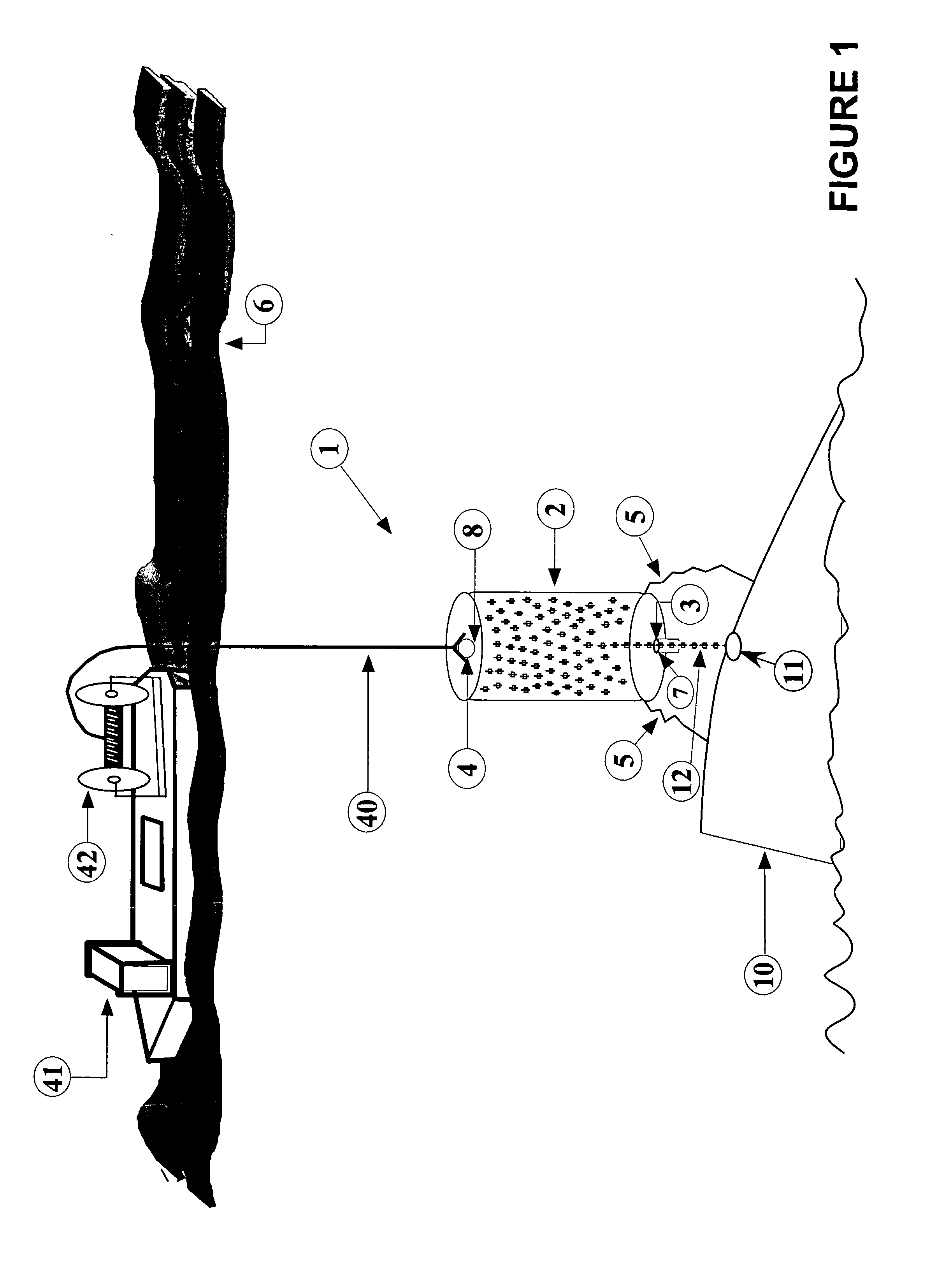
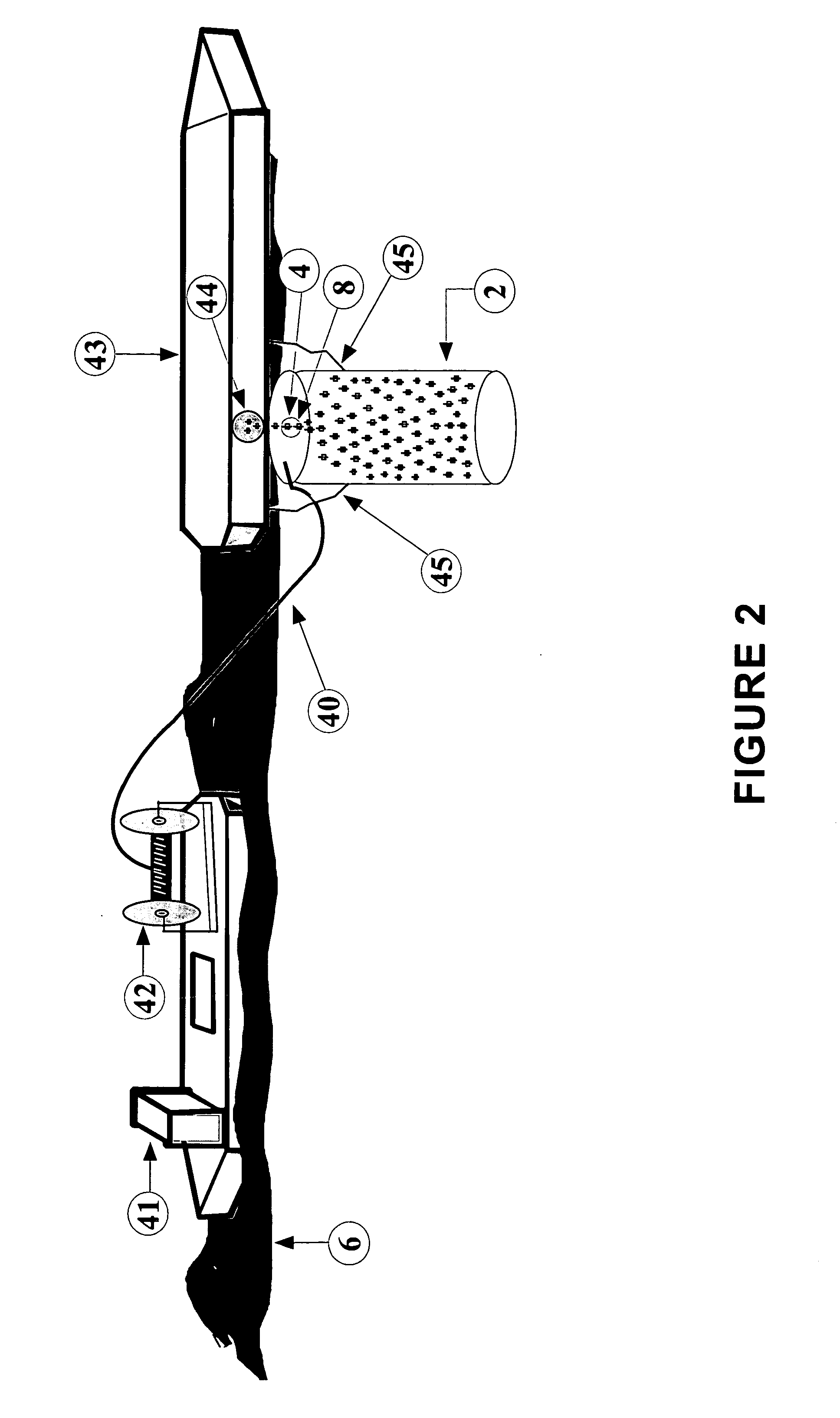
Subsea oil collector
- Summary
- Abstract
- Description
- Claims
- Application Information
AI Technical Summary
Benefits of technology
Problems solved by technology
Method used
Image

Examples
Embodiment Construction
[0023] Unless otherwise noted herein, all construction materials are fluid impervious, and all attachments between such components are structurally sound. Materials and methods are intended to impart a maximum level of strength and structural rigidity, while keeping the invention as lightweight and easy to use as possible. Certain features which are used in assembling or operating the invention, but which are known to those of ordinary skill in the art and not bearing upon points of novelty, such as screws, bolts, nuts, welds, and other common fasteners, may not be shown for clarity.
[0024] In preparation for use of the invention to be described below, a large release hole 11 is cut into one of the tanks on the submerged tanker or other vessel 10 using an ROV (in deep water) or by divers (at depths enabling diver operations). Immediately after the release hole 11 is formed, a closure mechanism is immediately installed on the vessel 10, such as a magnetic cap, valve, or other suitabl...
PUM
 Abstract
Description
Claims
Application Information