Target guiding radar with continuous waves

A technology of target guidance and radar, which is applied in the field of continuous wave target guidance radar and intelligence command radar, which can solve the problems of complex technology implementation, high hardware cost, and precision error, and achieve large angle measurement range, low hardware cost, and convenient mobile use Effect

Active Publication Date: 2013-04-24
TIANWEI ELECTRONICS SYST ENG
View PDF7 Cites 18 Cited by
  • Summary
  • Abstract
  • Description
  • Claims
  • Application Information

AI Technical Summary

Problems solved by technology

In solving the measurement of radar target elevation angle and height, the principle of single-pulse intradyne angle measurement is generally used to realize the measurement of elevation angle. This angle measurement method belongs to the multi-beam technology of simultaneous beams. Because it is a simultaneous beam system, the same echo signal Received by the upper and lower beams at the same time, the angle information is only retained in the ratio of the two echoes, which has nothing to do with the strength of the echo, which avoids the error caused by the fluctuation of the echo, so the accuracy of the angle measurement is compared High, but in this way, the angle measurement range is limited by the beam width and the deviation angle formed by the two beams, and the angle measurement range is theoretically limited between the two outer 3dB points of the upper and lower beams
In order to expand the coverage of the beam, based on the fact that two beams cannot effectively meet the requirements of the coverage of the beam, the use of multiple beams is an effective solution, but the more beams, the more complicated the technical implementation, and the corresponding hardware cost becomes high.

Method used


Image

  • Target guiding radar with continuous waves
  • Target guiding radar with continuous waves
  • Target guiding radar with continuous waves

Examples


Embodiment Construction

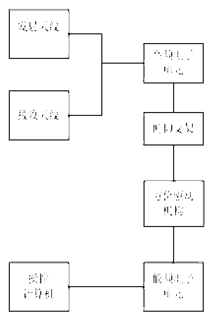
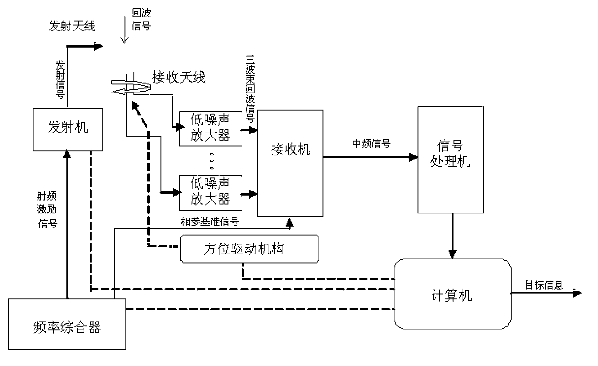
[0028] like figure 1 , figure 2 As shown, the continuous wave target guidance radar of the present invention includes a transmitting antenna, a receiving antenna, a high-frequency electronic unit, a low-frequency electronic unit, an elevation mechanism, an azimuth drive mechanism and a computer;

[0029] The transmitting antenna and the receiving antenna form an array antenna, wherein:

[0030] The transmitting antenna is used to receive the transmitting signal sent by the transmitter through the feeder, and radiate the transmitting signal to space to form a shaped beam. In this embodiment, the transmitting antenna adopts a waveguide array antenna, which is designed according to the shape. By adjusting the phase between each waveguide, the antenna forms a cosecant square characteristic on the elevation plane.

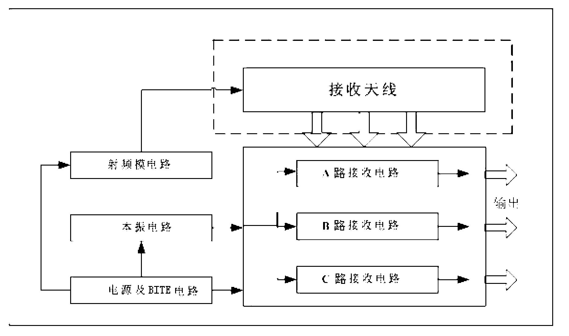
[0031] The receiving antenna is used to receive the echo signal reflected by the air target, amplify the received echo signal through the low noise amplifier connect...


PUM


Abstract

The invention discloses a target guiding radar with continuous waves. The target guiding radar with the continuous waves comprises transmitting antenna and receiving antenna, a high frequency electronic unit, a luffing mechanism, an azimuth driving mechanism, a low frequency electronic unit and a computer. The middle portion on the back of antenna array is fixedly connected with the high frequency electronic unit. The high frequency electronic unit is arranged on the luffing mechanism. The luffing mechanism is connected with the azimuth driving mechanism. The integration which is composed of the antenna array, the high frequency electronic unit and the luffing mechanism are driven by the azimuth driving mechanism to move along with the luffing mechanism. A transmitter is respectively connected with a frequency synthesizer and the transmitting antenna through a signal cable. A receiver is respectively connected with the frequency synthesizer, the receiving antenna and a signal processor through the signal cable. The antenna adopts array antenna, and the receiving antenna can receive three different direction luffing beams. The receiver respectively amplifies and filters a target echo through three routes. Due to the fact that the receiver produces a middle frequency signal in an intermediate frequency sampling working way, three-coordinates measuring to an aerial target is achieved.

Description

technical field [0001] The invention belongs to the field of electronic engineering, and in particular relates to an intelligence command radar, in particular to a continuous wave target guidance radar. Background technique [0002] At present, due to the low transmission power and adjustable frequency and power, the continuous wave target guidance radar has a certain low interception and anti-jamming ability in the complex electronic countermeasure environment, and has the technical advantages of small size, light weight, portability and mobile use. . In solving radar target elevation angle and height measurement, the principle of single-pulse intradyne angle measurement is generally used to realize the measurement of elevation angle. This angle measurement method belongs to the multi-beam technology of simultaneous beams. Because it is a simultaneous beam system, the same echo signal Received by the upper and lower beams at the same time, the angle information is only ret...

Claims


Application Information

Patent Timeline
Patent Type & Authority Applications(China)
IPC IPC(8): G01S13/42
Inventor 罗思明徐正平
Owner TIANWEI ELECTRONICS SYST ENG
Why Eureka
Try Eureka