Edge-carrying drill body having an internal chip-removal channel

a drill body and chip removal technology, applied in the field of drilling body, can solve the problems of plurality of bodies, difficult to master deep hole drilling, and excessive weakening of comparatively weak steel bodies,

Inactive Publication Date: 2005-02-03
SANDVIK INTELLECTUAL PROPERTY AB
View PDF28 Cites 42 Cited by
  • Summary
  • Abstract
  • Description
  • Claims
  • Application Information

AI Technical Summary

Benefits of technology

[0009] The present invention aims at obviating the above-mentioned disadvantages of previously known drill bodies for deep hole drilling and at providing an improved drill body. Therefore, it is a primary object of the invention to provide an edge-carrying drill body having a symmetrical geometry, which becomes selfing and which, therefore, may be manufactured without any problematic support strips.
[0010] An additional object is to provide a drill body having a chip evacuation channel, the chip inlets of which can be constructed with optimum width with the purpose of improving the chip breaking and counteracting the risk of chip stopping.
[0011] Yet another object of the invention is to provide a drill body that reduces the risk of total damage if the drill body were to become stuck in a work-piece.
[0012] It is also an object to provide a drill body that guarantees a good machining precision and that has a long service life.
[0013] An additional object of the invention is to provide a drill body, which during chip removal, generates chips of a reduced width in order to facilitate the chip evacuation.
[0015] The invention is based on the idea of manufacturing such drill bodies intended for deep hole drilling that have an internal through-channel for chip and cooling liquid removal, the body having a front bridge on which a plurality of integral edges are included, and in front of which—seen in the direction of rotation of the drill body—there are chip inlets to the channel. In practice, said bridge is advantageously made from cemented carbide or CERMET, wherein the bridge either may be included as an integrated part of the drill body in its entirety, or be made as a unit that in a suitable way is fixed on a rear unit of any material, e.g., steel. Due to the fact that the cutting edges are integrated in the bridge, in a simple way the drill body can be formed with a symmetrical cutting geometry, which makes the drill body selfing. In other words, any need for support strips on the outside of the drill body is eliminated.

Problems solved by technology

Within the field of chip forming machining, deep hole drilling constitutes an area difficult to master, in particular when the holes should be extraordinary long or deep.
However, at small diameters (9-25 mm), only soldered cutting inserts are possible because the requisite means for clamping detachable cutting inserts would complicate and weaken the comparatively weak steel body too much.
In both cases, however, not only the drill bodies as such, but also the manufacture of the same, are associated with a plurality of disadvantages.
One disadvantage is that the drill bodies have to be made with asymmetrical tool geometry where the drill tip is displaced or eccentric in relation to the geometrical center axis of the drill body.
The existence of said support strips may give rise, on one hand, to pressing-in of chips and particles in the machined hole surface, and on the other hand, to high pressure and high generation of heat as a consequence of the friction against the surrounding hole wall, which heat produces cracks in the cutting inserts and strong wear of the same.
Furthermore, the strips intrude on the width of the chip inlet(s); something that in turn increases the risk of chip stopping and inferior chip breaking.
Another disadvantage of the previously known drilling tools is that the same may be totally destroyed if the drill body becomes stuck in a workpiece, more precisely not only the front drill body but also the rear tube are demolished upon jamming.
It should also be pointed out that the precision of the drill bodies during machining may become mediocre, in particular after one or more exchanges of cutting inserts.
What is more, the production cost for the drill bodies is high as well as the cost for possible regrinding.
Moreover, not even an edge-carrying front bridge is included in such prior art that could bridge over such a channel.

Method used


Image

  • Edge-carrying drill body having an internal chip-removal channel
  • Edge-carrying drill body having an internal chip-removal channel
  • Edge-carrying drill body having an internal chip-removal channel

Examples


first embodiment

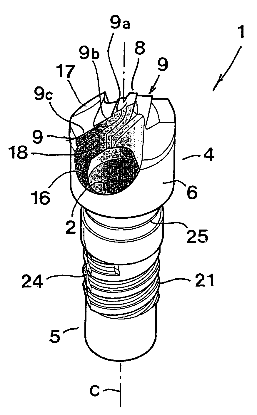
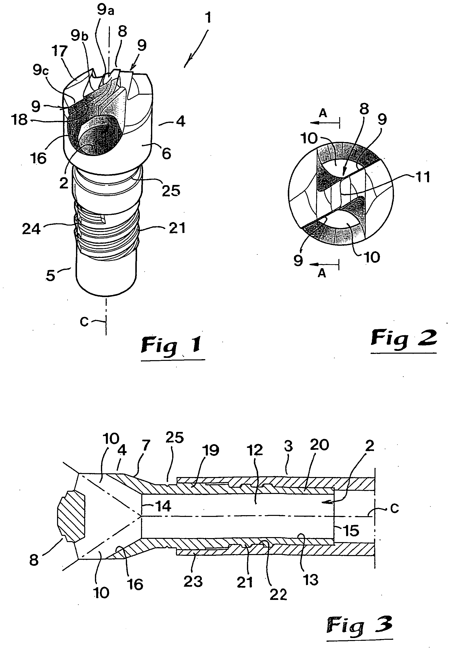
[0022] In FIGS. 1-2, there is shown an edge-carrying drill body 1, which is rotatable around a central geometric axis C and comprises a through-channel 2 arranged for internal chip evacuation. Said channel mouths (opens) in front and rear ends of the body 1 to form front and rear mouths, respectively.

[0023] The drill body 1 is connectable with a cylindrical tube 3 shown in FIG. 3, together with which tube the same forms an operative drilling tool of the type that, to those skilled in the art, is denominated STS drill (Single Tube System). Drills of this type are intended for deep hole drilling and are included in an extensive drilling equipment (or machine), which in the area of the rear end (not shown) of the tube 3 includes sealing devices via which cooling liquid can be introduced under pressure in the ring-shaped gap that is formed between the outside of the tube and a hole recessed by the drill body 1 in a workpiece. For this purpose, the tube 3 has an outer diameter that is sm...

second embodiment

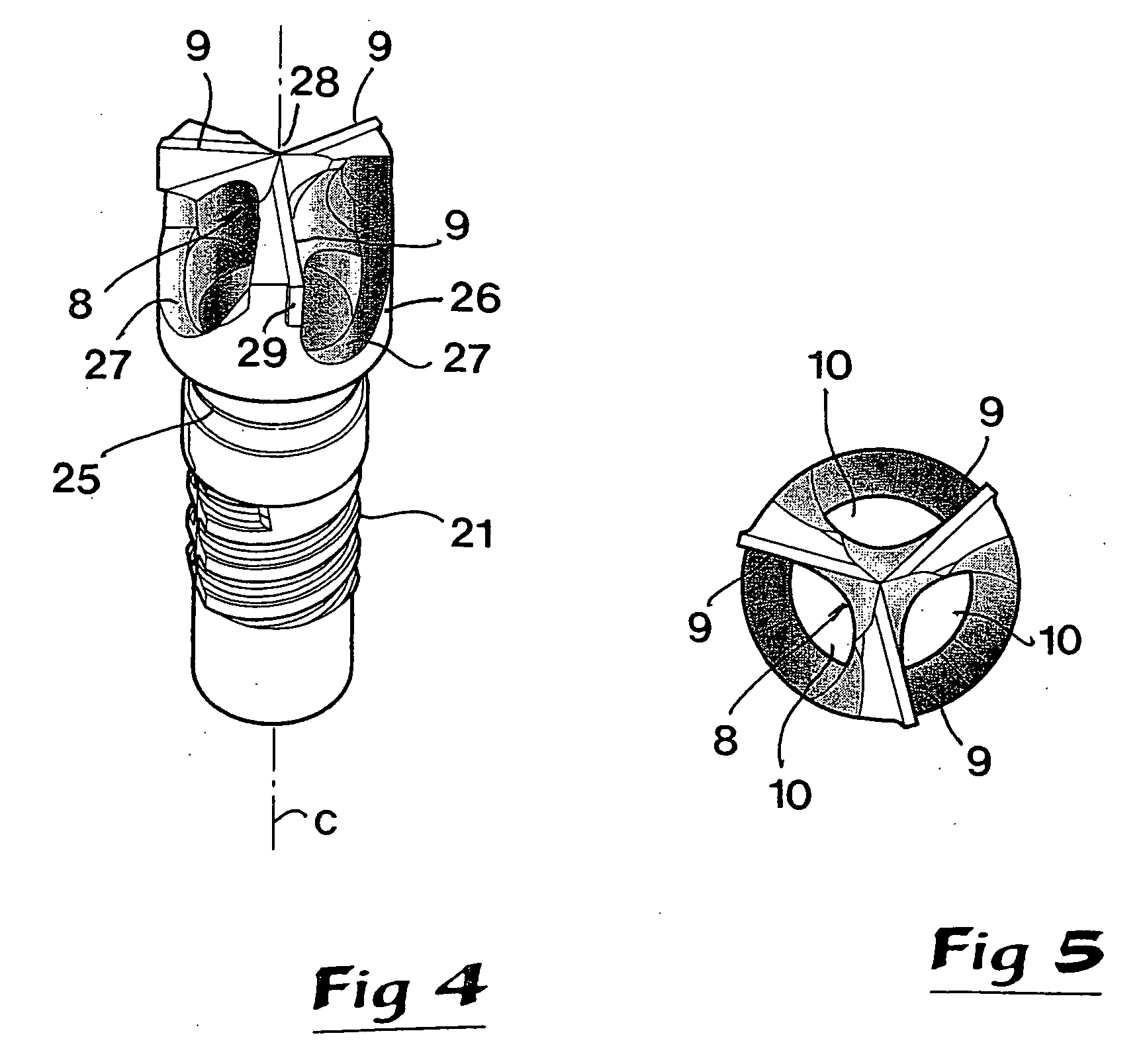
[0041] In FIGS. 4 and 5, a second embodiment is illustrated, according to which a bridge 8 bridging-over the chip channel opening is formed with three integrated cutting edges 9. Thus, in this case, the bridge includes three bars or bar-like material portions, which emanate from a central intermediate portion of a ring-shaped wall 26 in which three countersinks are formed, which form chip inlets 10 to the internal, through chip channel. The surface 27 defining each individual chip inlet 10 (see also the surface 16 in FIG. 1) is at least partially cone-shaped in order to facilitate the transportation of the chips into and through the inlet. The three bars together with the appurtenant edges are mutually equidistantly spaced-apart in the tangential direction, i.e., the separation between the same is 120°. The edges converge in a common point that forms a centering tip 28 located along the geometrical center axis C of the drill body. In the extension of the three edges, guides 29 are f...


PUM

PropertyMeasurementUnit
diametersaaaaaaaaaa
diametersaaaaaaaaaa
diametersaaaaaaaaaa

Abstract

An edge-carrying drill body intended for deep hole drilling, is rotatable around a central geometric axis and comprises a through-channel arranged for internal chip evacuation. The channel mouths in front and rear ends of the drill body. A front channel mouth is bridged-over by a bridge on which a plurality of cutting edges are formed, which edges are made integrally with the rest of the bridge. The front mouth includes inlets disposed in front of respective cutting edges with reference to the direction of rotation of the body.

Description

[0001] This application claims priority under 35 U.S.C. §§119 and / or 365 to Patent Application Serial No. 0301455-2 filed in Sweden on May 20, 2003, the entire content of which is hereby incorporated by reference. BACKGROUND OF THE INVENTION [0002] This invention relates to an edge-carrying drill body, which is rotatable around a central geometric axis and comprises a through channel that is arranged for internal chip evacuation and that mouths in front and rear ends of the body. DESCRIPTION OF THE PRIOR ART [0003] Within the field of chip forming machining, deep hole drilling constitutes an area difficult to master, in particular when the holes should be extraordinary long or deep. By long holes, holes having a relatively great ratio of hole depth to hole diameter (D) are intended, e.g., hole depths of from 5×D up to 100×D or more. For the machining in question, drilling tools of two different main categories are used, viz, so-called ejector drills and STS drills (Single Tube Syste...

Claims


Application Information

Patent Timeline
Patent Type & Authority Applications(United States)
IPC IPC(8): B23B51/00B23B51/04B23D
CPCB23B51/048B23B2222/16B23B2222/84B23B2251/02B23B2251/14B23B2251/202Y10T408/909B23B2260/138Y10S408/705Y10T408/45Y10T408/455Y10T408/9095B23B2251/422B23B51/063B23B51/00
Inventor LINDBLOM, STEFAN
Owner SANDVIK INTELLECTUAL PROPERTY AB
Why Eureka
Try Eureka