Fluid over-flow/make-up air assembly for reprocessor

a technology of makeup air and overflow block, which is applied in the direction of combination devices, fluid pressure control, water/sewage treatment, etc., can solve the problem that the filtering of the incoming air does not insure sterile conditions

Active Publication Date: 2005-02-03
AMERICAN STERILIZER CO
View PDF6 Cites 11 Cited by
  • Summary
  • Abstract
  • Description
  • Claims
  • Application Information

AI Technical Summary

Benefits of technology

[0011] An advantage of the present invention is a combination fluid over-flow block/make-up air assembly for use in a reprocessor.
[0012] Another advantage of the present invention is a fluid over-flow block/make-up air assembly that maintains sterile conditions between the make-up air filter and a sterilization chamber of a reprocessor.
[0013] A still further advantage of the present invention is a replaceable filter assembly that is mountable to the fluid over-flow block in

Problems solved by technology

A problem with such air purge/fluid overflow assembly and air make-up assemblies is preventing biological contaminants from entering the chamber (and container) when external air is drawn into the chamber after a sterilization or deactivation cycle

Method used


Image

  • Fluid over-flow/make-up air assembly for reprocessor
  • Fluid over-flow/make-up air assembly for reprocessor
  • Fluid over-flow/make-up air assembly for reprocessor

Examples


Embodiment Construction

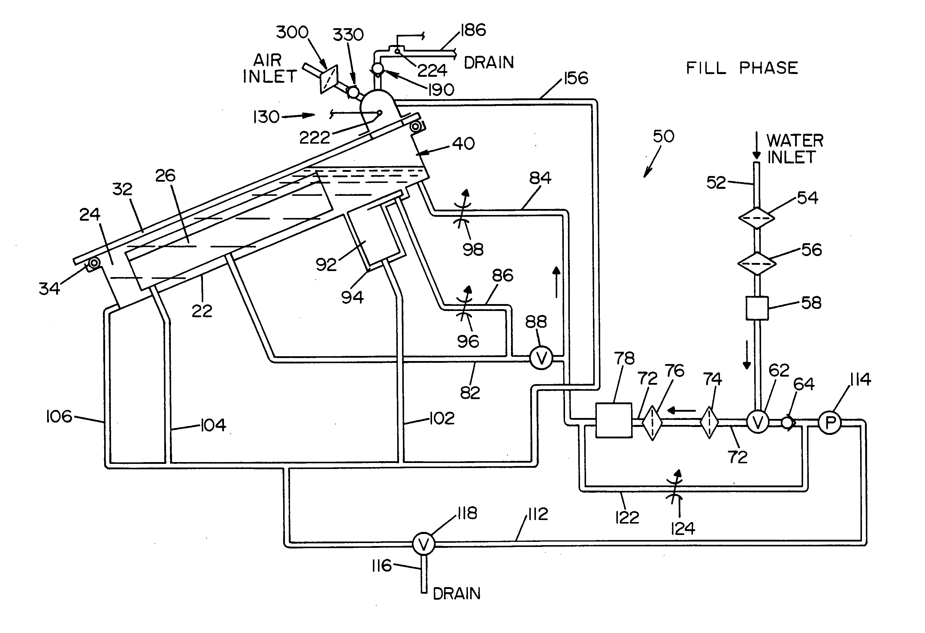
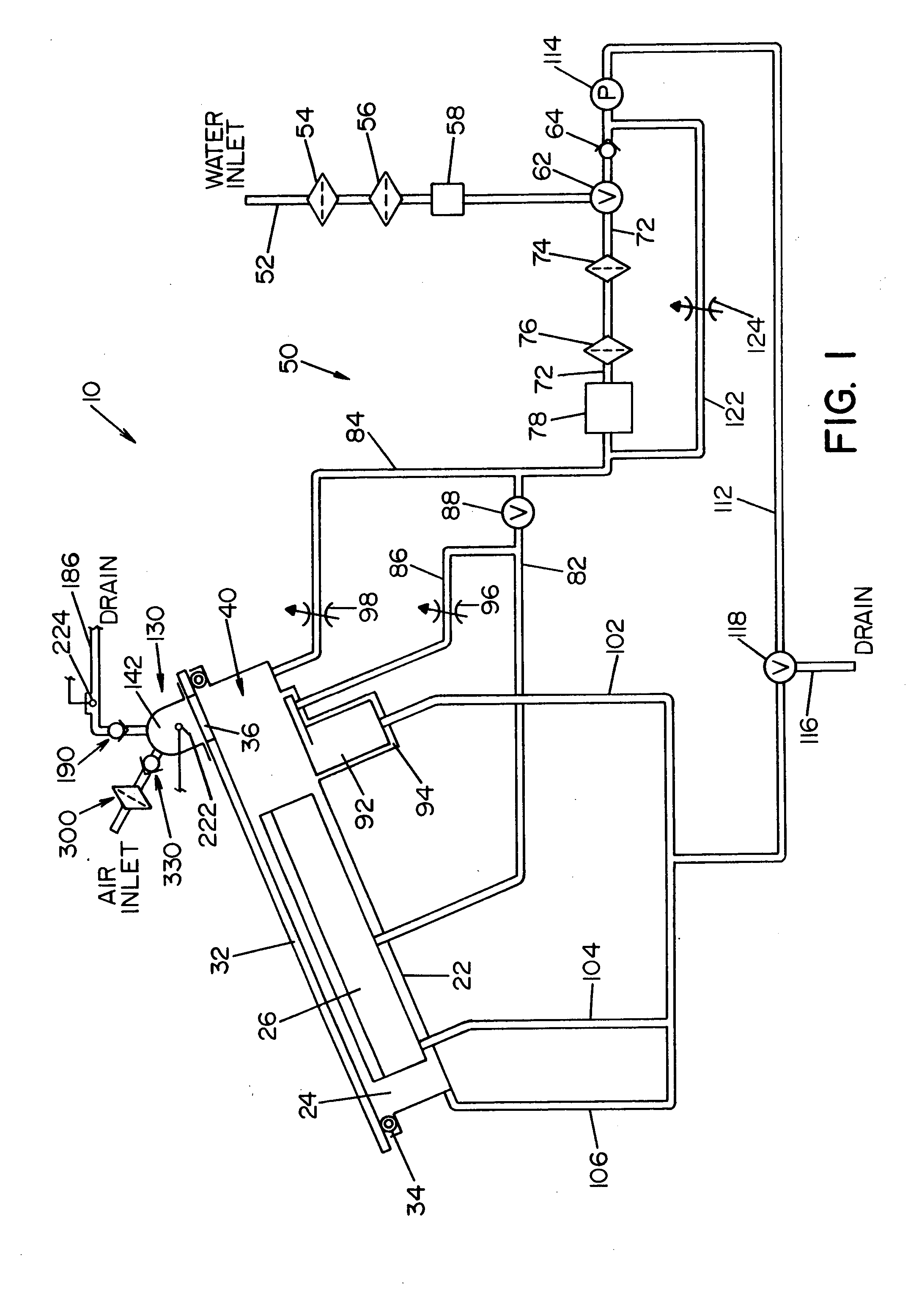
[0027] Referring now to the drawings wherein the showings are for the purpose of illustrating a preferred embodiment of the invention only, and not for the purpose of limiting same, FIG. 1 shows a simplified, schematic piping diagram of a microbial deactivation apparatus 10 having a fluid over-flow block / make-up air assembly, illustrating a preferred embodiment of the present invention.

[0028] Panel 22, that is part of a housing structure (not shown), defines a recess or cavity 24 dimensioned to receive items or instruments to be microbially deactivated. In the embodiment shown, a tray or container 26 is provided to receive the devices or instruments to be deactivated. Container 26 is dimensioned to be received within the recess or cavity 24, as illustrated in FIG. 1.

[0029] A manually operable lid 32 is movable between an opened position allowing access to cavity 24, and a closed position (shown in FIG. 1) closing or covering cavity 24. Seal element 34 surrounds cavity 24 and forms...


PUM

PropertyMeasurementUnit
Efficiencyaaaaaaaaaa
Pressureaaaaaaaaaa
Flow rateaaaaaaaaaa

Abstract

A system for sterilizing or microbially deactivating instruments and devices. The system includes a circulation system for circulating a microbial deactivation fluid through a chamber for containing the instruments and devices. The chamber forms a portion of the circulation system. The system further includes a fluid over-flow/make-up air assembly. The fluid over-flow/make-up air assembly includes a manifold having an inner cavity that is in fluid communication with the circulation system, an overflow port in the manifold, and an overflow valve assembly disposed in the manifold allowing fluid flow from the cavity to the overflow port when a pressure in the cavity exceeds a pressure in the overflow port by a predetermined amount. A filter assembly is attached to the manifold. The filter assembly has a filter valve assembly in communication with the cavity. The filter assembly is operable to allow air through the filter assembly into the cavity when the pressure within the cavity is a predetermined amount less than the pressure within the filter assembly.

Description

FIELD OF THE INVENTION [0001] The present invention relates to the microbial deactivation of medical, dental, pharmaceutical, veterinary or mortuary instruments and devices, and more particularly to a fluid over-flow block with makeup-air assembly for use in a microbial deactivation system. BACKGROUND OF THE INVENTION [0002] Medical, dental, pharmaceutical, veterinary or mortuary instruments and devices that are exposed to blood or other body fluids require thorough cleaning and anti-microbial deactivation or sterilization between each use. Liquid microbial deactivation systems are now widely used to clean and deactivate instruments and devices that cannot withstand the high temperatures of a steam sterilization system. Liquid microbial deactivation systems typically operate by exposing the medical devices and / or instruments to a liquid disinfectant or sterilization composition, such as peracetic acid or some other strong oxidant. [0003] In such systems, the instruments or devices t...

Claims


Application Information

Patent Timeline
IPC IPC(8): A61L2/02A61L2/16A61L2/18A61L9/16C02F1/00C02F1/44C02F1/50C02F1/68C02F9/00
CPCA61L2/022A61L2/18C02F2301/08C02F2209/005C02F2103/026C02F9/00A61L9/16C02F1/444C02F1/50C02F1/688C02F1/001C02F1/32C02F1/44A61L2202/10
Inventor JETHROW, CHRISTOPHER A.KRAL, JUDE A.SARGENT, DONALD A.
Owner AMERICAN STERILIZER CO
Why Eureka
Try Eureka