
Valve holding fixture for automated reprocessor

a technology of automatic reprocessor and valve holding fixture, which is applied in the direction of cleaning hollow objects, application, cleaning using liquids, etc., can solve the problems of inability to adequately clean and deactivate the valves used in the endoscope, process undesirable, and exposure to contamination

Active Publication Date: 2005-04-05
STERIS CORP
View PDF13 Cites 9 Cited by
  • Summary
  • Abstract
  • Description
  • Claims
  • Application Information

AI Technical Summary

Benefits of technology

An advantage of the present invention is a means for cleaning a valve assembly that does not require operator exposure to the valve assembly during the cleaning and sterilization process.
is a means for cleaning a valve assembly that does not require operator exposure to the valve assembly during the cleaning and sterilization process.
Another advantage of the present invention is a fixture for cleaning a valve assembly from an endoscope or the like in an automated reprocessing system.
Another advantage of the present invention is a fixture for cleaning valve assemblies from an endoscope and the like that maintains the valve assembly in a position exposing all surfaces of the valve assembly to the cleaning and disinfecting solutions.
Another advantage of the present invention is a fixture for cleaning a valve assembly from an endoscope or the like that allows complete reprocessing of a valve assembly during a single, regular reprocessing operation.
These and other advantages will become apparent from the following description of a preferred embodiment taken together with the accompanying drawings and the appended claims.

Problems solved by technology

A problem with such systems is that they cannot adequately clean and deactivate the valves used within the endoscope.
Such a process is undesirable in that it requires an operator to physically handle the valve assembly and thus be exposed to any contamination thereon.
Moreover, such a cleaning process is subjected to human error, and it is difficult to establish the efficacy of such a cleaning process.
None of these methods of cleaning guarantees that the contacting surfaces of the valve assemblies are separated from each other, and are thoroughly exposed to the cleaning and disinfecting solution during a reprocessing operation.
Moreover, reprocessing that requires special or repeated cleaning and disinfecting cycles is not economically desirable to a customer.

Method used


Image

  • Valve holding fixture for automated reprocessor
  • Valve holding fixture for automated reprocessor
  • Valve holding fixture for automated reprocessor

Examples


Embodiment Construction

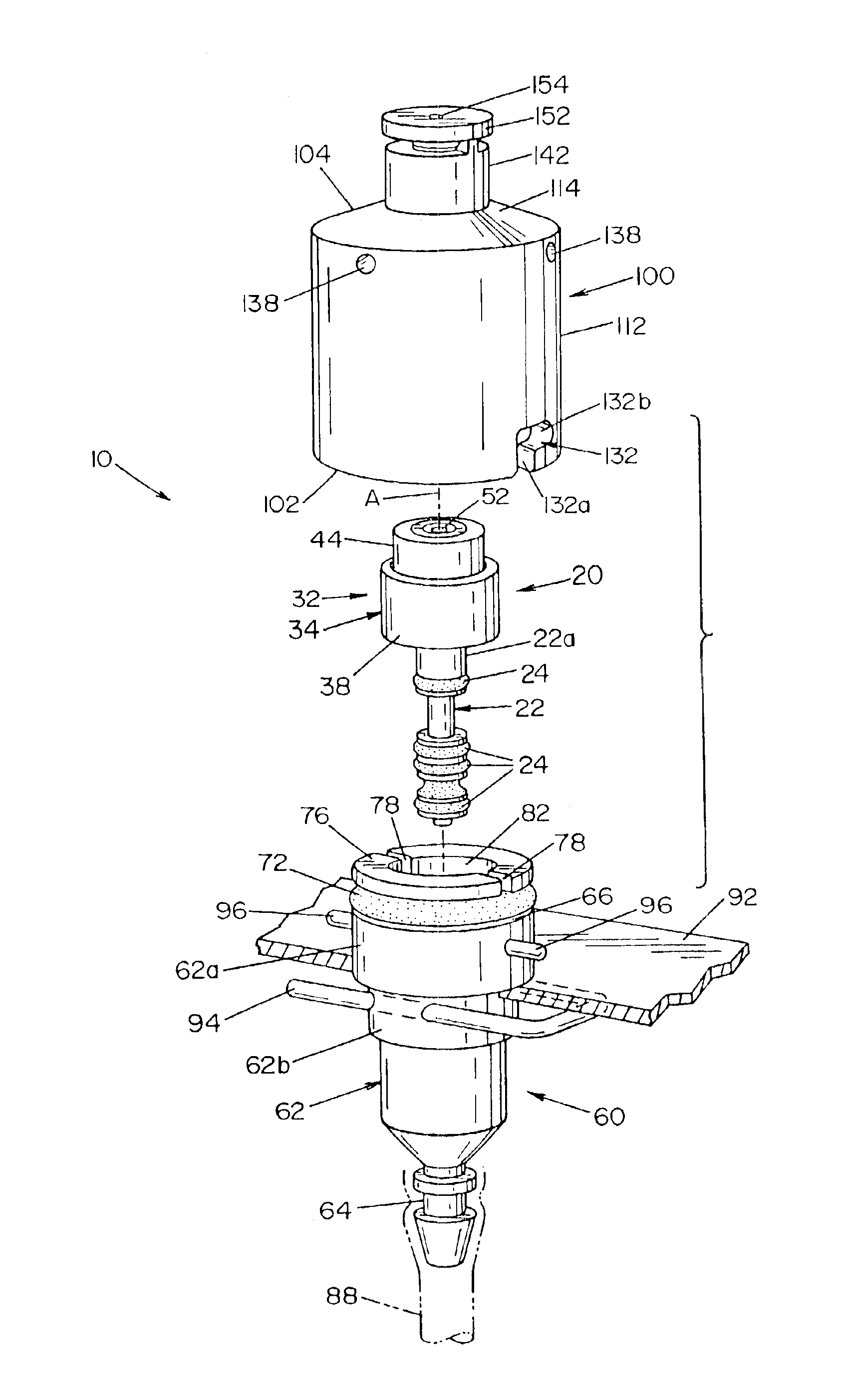
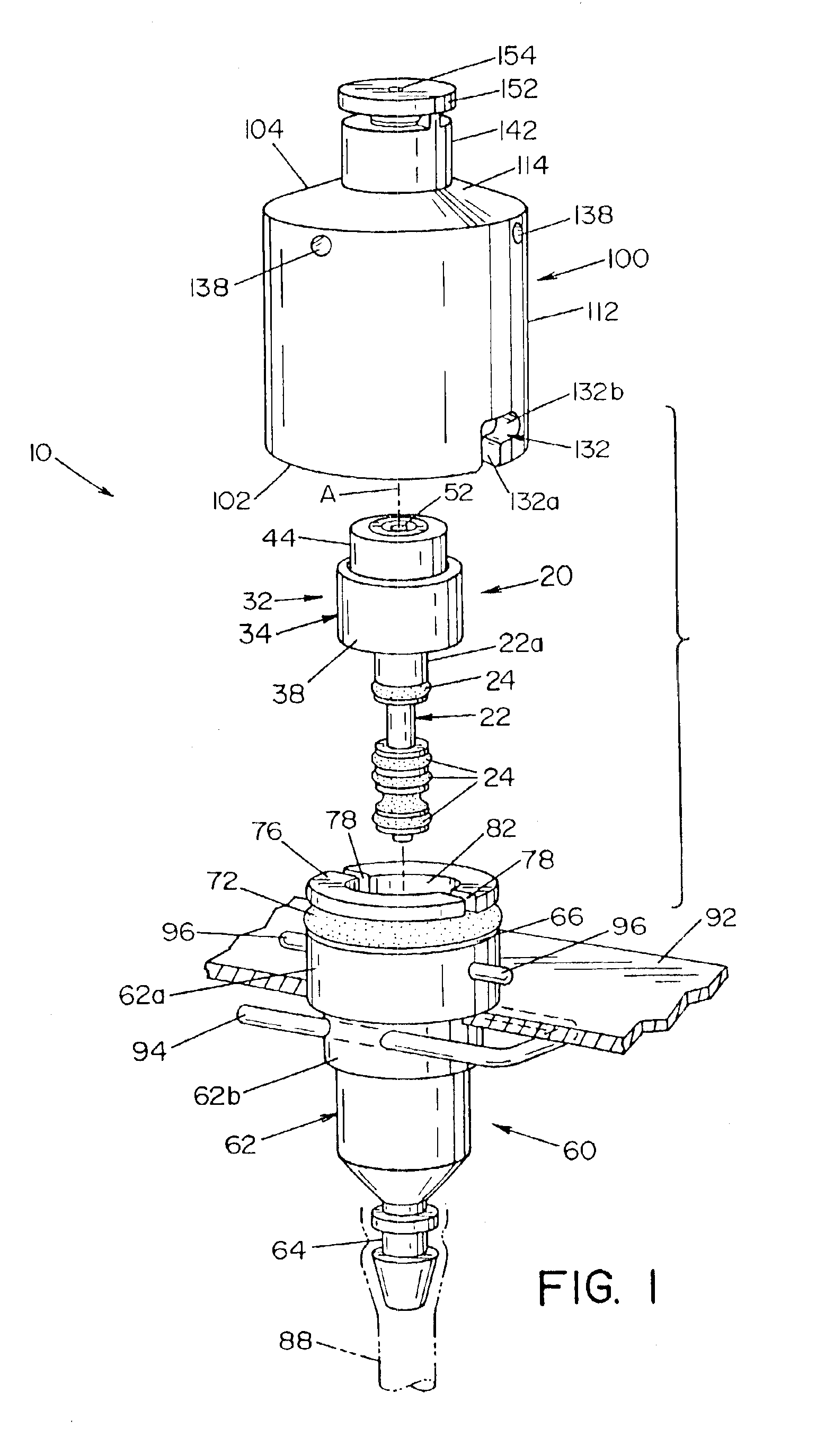
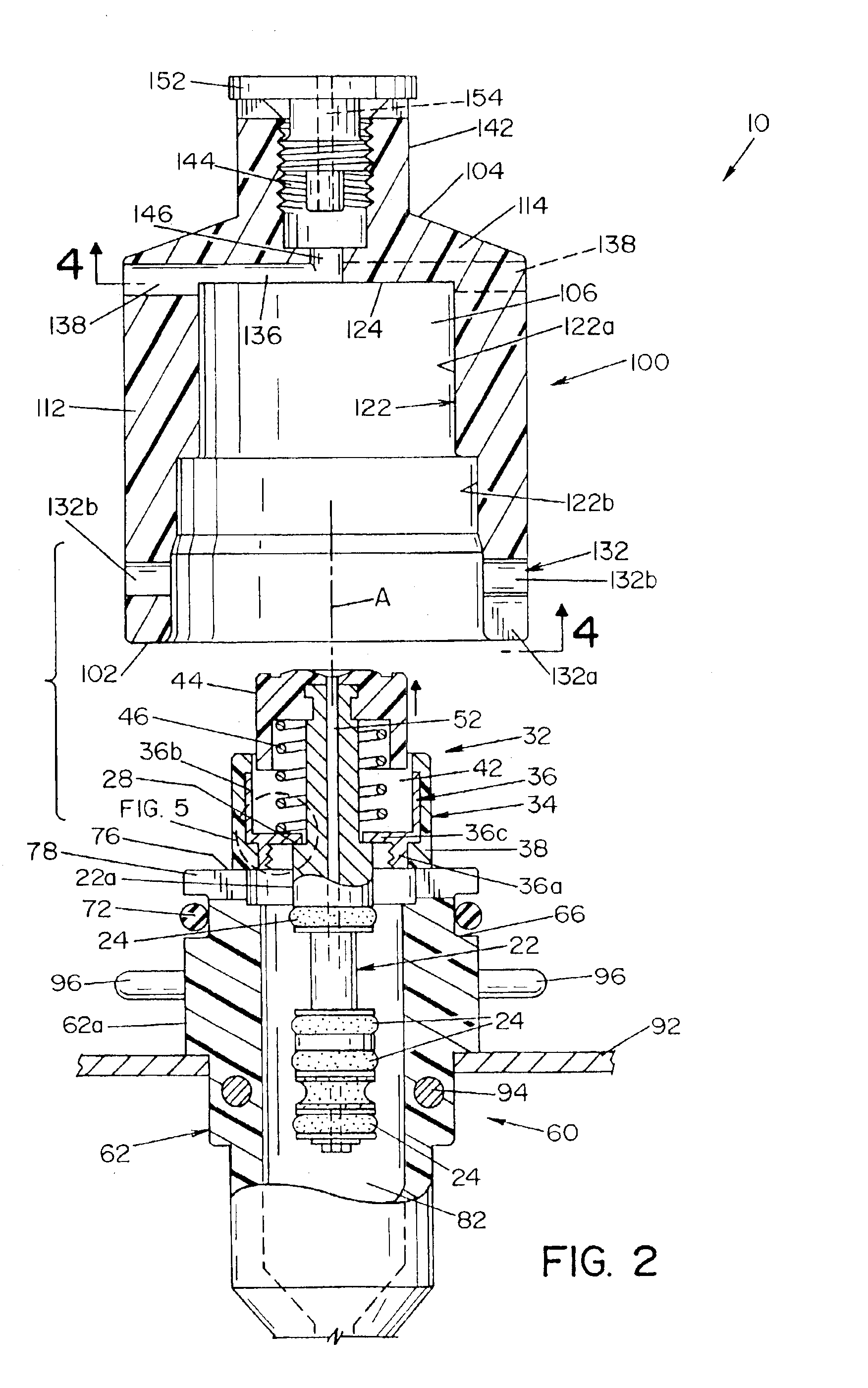
Referring now to the drawings wherein the showings are for the purpose of illustrating the preferred embodiment of the invention only, and not for the purpose of limiting same, FIG. 1 shows a fixture 10 for supporting a valve assembly 20 from a medical instrument, such as an endoscope or the like, in an automated reprocessor, illustrating a preferred embodiment of the present invention.

Valve assembly 20 in and of itself forms no part of the present invention, but shall be described to provide a better understanding of fixture 10 and its operation. Valve assembly 20, as shown in the drawings, is representative of a typical valve assembly found in an endoscope or other similar medical devices. Valve assembly 20 is essentially comprised of an elongated valve stem 22 having a valve actuating assembly 32 at one end and a plurality of spaced-apart O-rings 24 at the other end. Valve actuating assembly 32, best seen in FIGS. 2 and 3, is basically comprised of a collar 34 that is adapted to ...


PUM


Abstract

A fixture for holding a valve assembly in an automated washing system, wherein the valve assembly is movable between an opened position and a normally closed position. The fixture is comprised of first and second housing sections that are releaseably attachable to each other. The housing sections define an internal cavity that is dimensioned to hold the valve assembly in an opened position. A fluid inlet is in communication with the chamber, and is attachable to a source of an anti-microbial fluid in the washing system. A fluid outlet communicates with the chamber to allow the anti-microbial fluid to exit the fixture.

Description

FIELD OF THE INVENTIONThe present invention relates generally to the field of disinfection or sterilization of medical, dental, pharmaceutical or mortuary objects and devices, and more particularly to disinfection and sterilization of flexible endoscopes and parts and fittings therefore.BACKGROUND OF THE INVENTIONAn endoscope is an instrument equipped with a lighting and lens system used typically by physicians for visual examination of the interior of a body organ or cavity. Endoscopes include valves that are used by the physician to open and close air / water channels and suction / biopsy channels in the endoscope. During an endoscopic procedure, the instrument becomes coated with blood and other protein-rich body fluids, requiring that the endoscope undergo a thorough cleaning and anti-microbial deactivation between each use. Liquid microbial deactivation systems are now widely used to clean and deactivate equipment, such as endoscopes, that could not withstand the high temperatures ...

Claims


Application Information

Patent Timeline
IPC IPC(8): A61L2/00A61L2/24A61B1/12A61L2/18B08B11/00B08B9/00B08B11/02
CPCA61B1/00068A61B1/123A61B1/125A61B19/34A61B1/00137A61L2/18A61L2/24B08B9/00B08B11/02A61B2019/343A61B90/70A61B2090/701A61L2/00B08B3/08
Inventor HALSTEAD, ERICMCDONNELL, GERALD E.PRIEST, ROBERT M.
Owner STERIS CORP
Learn More