Tripod constant velocity universal joint
a constant velocity, universal joint technology, applied in the direction of yielding couplings, couplings, mechanical devices, etc., can solve the problems of increasing the size of the shell of the outer joint member, obstructing the improvement of life and the reduction of vibration, and the wear of the roller guide surface to proceed, so as to reduce vibration, without aggravating the vibration characteristics
- Summary
- Abstract
- Description
- Claims
- Application Information
AI Technical Summary
Benefits of technology
Problems solved by technology
Method used
Image
Examples
first embodiment
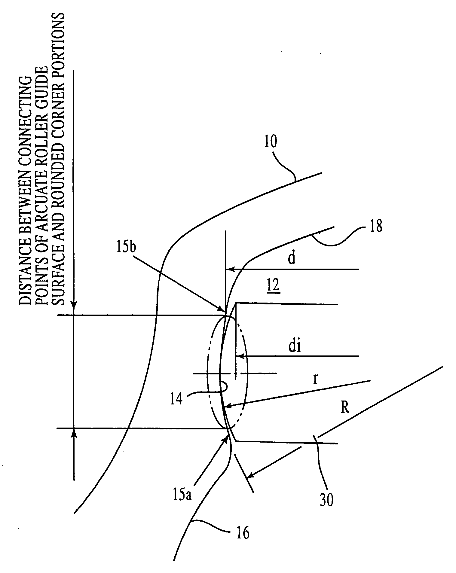
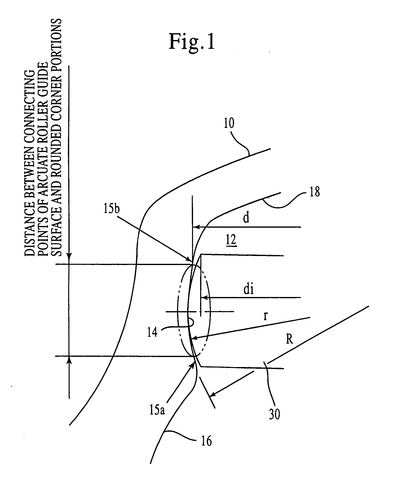
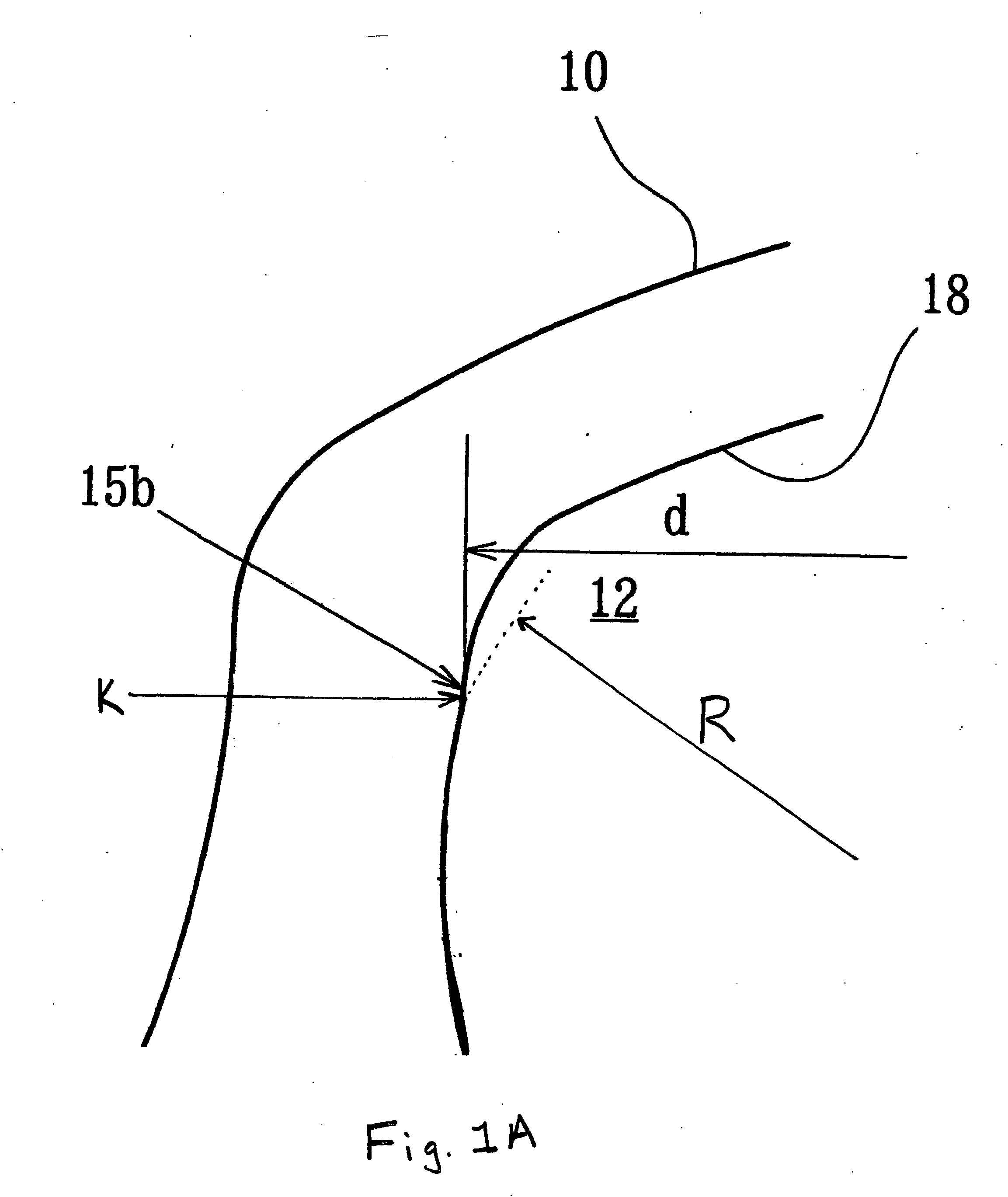
Referring to FIGS. 1 through 3C, the present invention will be described.
As shown in FIGS. 2A and 2B, a tripod constant velocity universal joint has, as main components, an outer joint member 10 which connects to one of two rotary shafts to be connected, and a tripod unit (20, 30, 32) which connects to the other rotary shaft.
The outer joint member 10 is in the form of a hollow cup having three axially extending circumferentially equispaced track grooves 12. Each track groove 12 has roller guide surfaces 14 formed in the opposed side walls thereof. This roller guide surface 14 is part of a cylindrical surface, i.e., a partial cylindrical surface, parallel with the axis of the outer joint member 10. The cross section of the outer joint member 10 is, as shown in FIG. 3A, in the form of a corolla in which circumferentially alternately appearing minor inner diameter portions 16 of diameter D1 and major inner diameter portions 18 of diameter D2 are connected by the roller guide surface...
second embodiment
of the present invention will now be described with reference to FIGS. 6 and 7.
The first and second embodiments are the same as far as the basic construction of tripod joint is concerned and as previously described in connection with FIGS. 2A, 2B, 3A, 3B, and 3C. Here, the outer peripheral surface of the roller 30 may be a partial spherical surface with its center of curvature located on the axis; besides this, it may be a convexly curved surface using an arc as its generating line with its center of curvature located at a position radially spaced from the axis. The form of contact of the roller 30 with the roller guide surfaces 14 may be angular contact as shown in FIG. 5A or circular contact as shown in FIG. 5B. Angular contact has a certain contact angle and occurs at two points, so that contact ellipses occur at two points in the direction of contact angle. Circular contact occurs between spherical surfaces and at one point. In either case, it is necessary to set the width Ls o...
third embodiment
the present invention, taking notice of the facts that the conventional tripod joints are designed with particular attention paid to the aspect of strength, particularly the strength of the shaft and that in the aspect of durability there is some room in the ordinary use, while considering balance between strength and durability, reduces the size of the shell of the outer joint member as much as possible, thus achieving weight reduction and compactification of the tripod joint. In the aspect of strength, the shaft and the tripod member are made substantially equal in strength and in the aspect of durability, notice is taken of the contact surface pressure between the needle rollers and the trunnion journal, and this surface pressure is allowed up to a predetermined value, whereby a radically compact design of an outer joint member has been achieved.
In the aspect of durability, notice is taken of contact surface pressure in the trunnion journal and the contact surface pressure in th...
PUM
 Abstract
Description
Claims
Application Information
 - R&D
- Intellectual Property
- Life Sciences
- Materials
- Tech Scout
- Unparalleled Data Quality
- Higher Quality Content
- 60% Fewer Hallucinations
Browse by: Latest US Patents, China's latest patents, Technical Efficacy Thesaurus, Application Domain, Technology Topic, Popular Technical Reports.
© 2025 PatSnap. All rights reserved.Legal|Privacy policy|Modern Slavery Act Transparency Statement|Sitemap|About US| Contact US: help@patsnap.com


