Tensioning or deflection pulley for a belt drive

Inactive Publication Date: 2005-02-03
INA SCHAEFFLER KG
View PDF9 Cites 46 Cited by
  • Summary
  • Abstract
  • Description
  • Claims
  • Application Information

AI Technical Summary

Benefits of technology

[0010] According to another feature of the present invention, the first sealing element may also be configured in the form of a cap cover having an axially inwardly directed rim portion formed with a locking element for securement to the inner ring, and a bottom portion, and an elastic seal may be provided to extend axially inwardly from the bottom portion of the first sealing element at a marginal area thereof, with the seal having a sealing lip resting against an adaptation surface of the inner ring. Thus, the first sealing element exhibits the same advantages as the second sealing element. In other words, the first sealing element is easy to produce and effectively protects the bearing for the pulley on the carrier-distal side.
[0011] According to another feature of the present invention, the carrier may be configured to have a hub and a carrier portion which extends radially outwardly from the hub and ends in an axially inwardly directed flange. Suitably, the carrier is spaced at a slight distance to the second sealing element to define a gap therebetween. More specifically, the gap may be defined between the radially outwardly directed portion of the carrier

Problems solved by technology

This conventional pulley suffers shortcomings arising from ingress of dirt because the sliding seals that are integrated in the rolling-contact bearing are unable to fully protect the interior.
Dirt can thus migrate into the bearing region of the pulley and thereby significantly r

Method used


Image

  • Tensioning or deflection pulley for a belt drive
  • Tensioning or deflection pulley for a belt drive

Examples


Example

[0016] The depicted embodiment is to be understood as illustrative of the invention and not as limiting in any way. It should also be understood that the drawings are not necessarily to scale and that the embodiments are sometimes illustrated by graphic symbols, phantom lines, diagrammatic representations and fragmentary views. In certain instances, details which are not necessary for an understanding of the present invention or which render other details difficult to perceive may have been omitted.

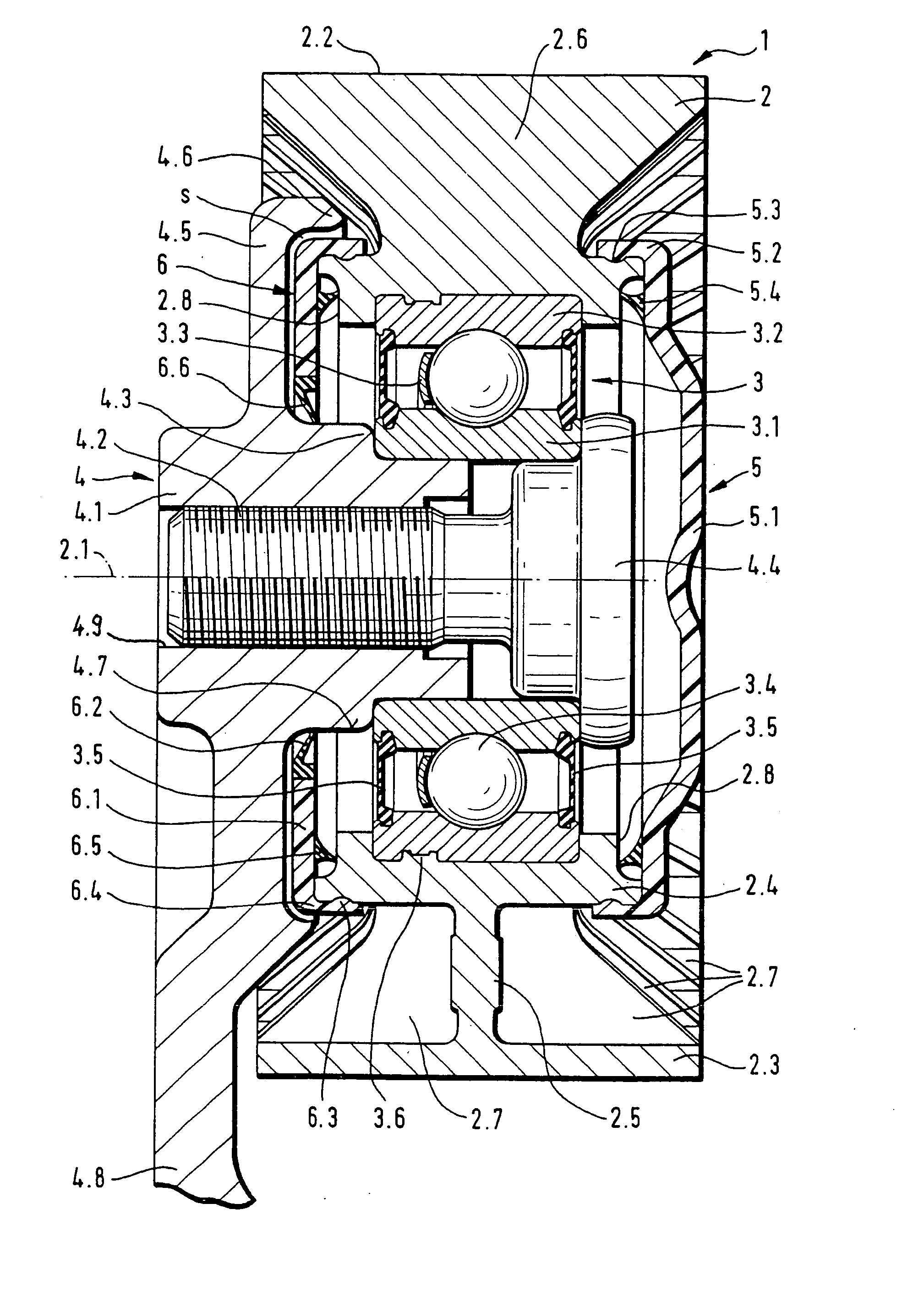
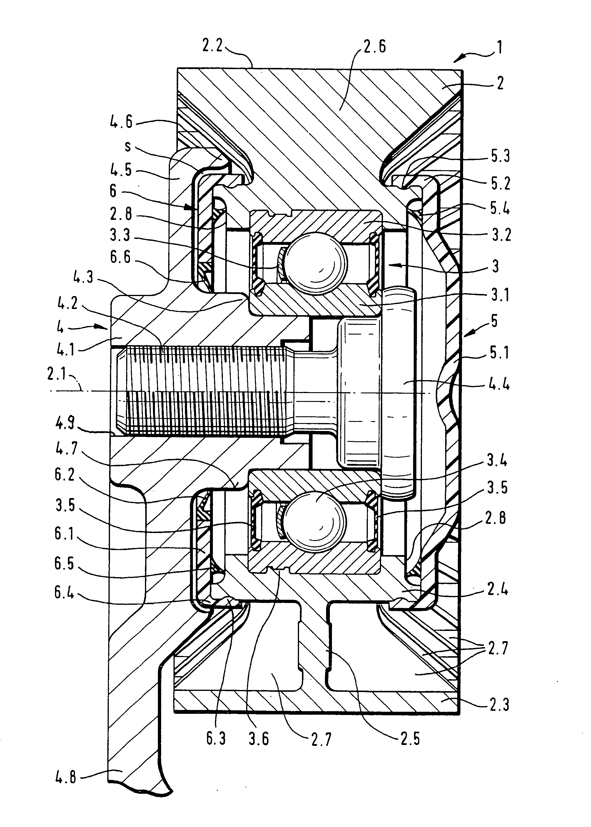
[0017] Turning now to FIG. 1, there is shown a longitudinal section of a tensioning or deflection pulley according to the present invention, generally designated by reference numeral 1. The pulley 1 defines an axis 2.1 and includes a track roller 2 and a rolling-contact bearing 3 for supporting the track roller 2 on a carrier 4 for rotation about the axis 2.1. The track roller 2 has an outer surface area 2.2 in contact with a belt (not shown) and has a double-T-shaped configuration with ...


PUM


Abstract

A tensioning or deflection pulley for a belt drive includes a carrier and a track roller comprised of an inner ring, an outer ring, and a connecting assembly, including a wheel disk extending between the inner and outer rings, and a rib assembly disposed in both sides of the disk in circumferential spaced-apart relationship, for interconnecting the inner and outer rings. The track roller is supported on the carrier by a sealed rolling-contact bearing via a fastening screw. A first sealing element is connected to the track roller on a carrier-distal side, and a second cap-shaped sealing element is disposed between the carrier and the track roller and detachably secured to the inner ring of the track roller to thereby seal the track roller on both sides.

Description

CROSS-REFERENCES TO RELATED APPLICATIONS [0001] This application is a continuation of prior filed copending PCT International application no. PCT / EP03 / 01005, filed Feb. 1, 2003, which designated the United States and on which priority is claimed under 35 U.S.C. §120, the disclosure of which is hereby incorporated by reference, and which claims the priority of German Patent Application, Serial No. 102 09 673.2, filed Mar. 5, 2002, pursuant to 35 U.S.C. 119(a)-(d).BACKGROUND OF THE INVENTION [0002] The present invention relates, in general, to a tensioning or deflection pulley for a belt drive. [0003] Nothing in the following discussion of the state of the art is to be construed as an admission of prior art. [0004] German patent publication DE 32 40 075 A1 describes a tensioning or defection pulley having a wheel disk which is rotatably mounted via a sealed rolling-contact bearing to a carrier. The wheel disk has a double-T-shaped cross section with an inner ring and an outer ring, wh...

Claims


Application Information

Patent Timeline
IPC IPC(8): F16C13/00F16C33/72F16C33/76F16H7/08
CPCF16C13/006F16C33/723F16C33/76F16C2361/63F16H2007/0865F16H7/20F16C33/7896F16C35/067F16C19/06
Inventor SCHENK, RAINERLUTKIC, ALEKSANDAR
Owner INA SCHAEFFLER KG
Why Eureka
Try Eureka