
Cryoablation systems and methods

a cryoablation system and system technology, applied in the field of cryoablation systems and methods, can solve the problems of prolonged abnormal cardiac rhythms or arrhythmias, pain and prolongation of recovery time for invasive surgery

Inactive Publication Date: 2005-02-03
CRYOCOR
View PDF65 Cites 74 Cited by
  • Summary
  • Abstract
  • Description
  • Claims
  • Application Information

AI Technical Summary

Benefits of technology

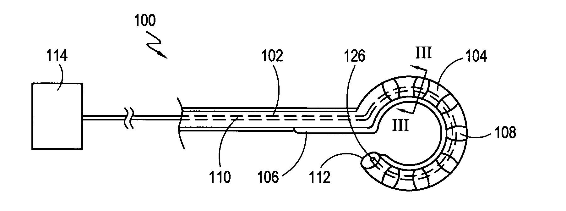
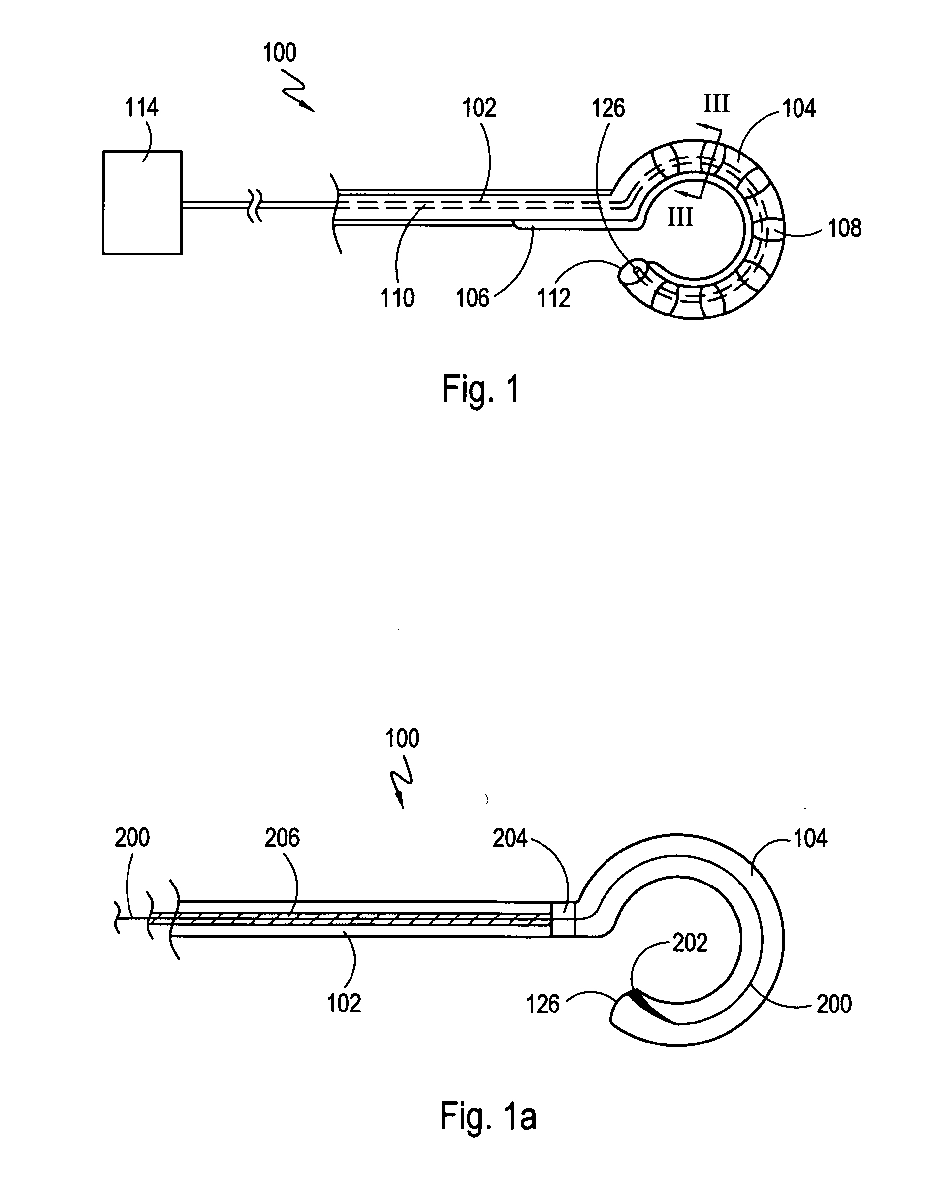
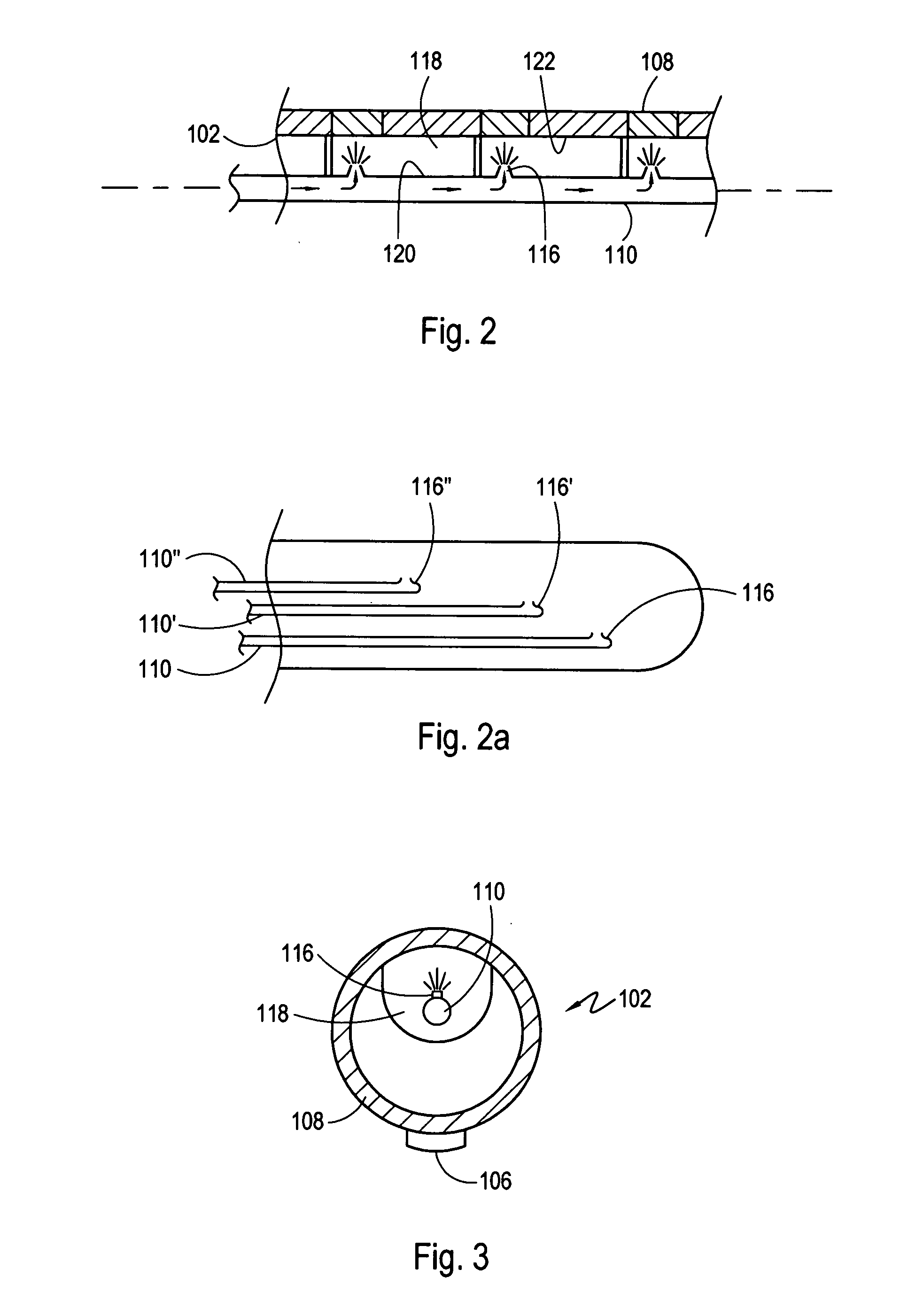
[0006] The present invention is directed to systems and methods for ablating tissue of a patient. For the present invention, the system includes a substantially rigid sheath and an elongated cryoablation catheter that defines an axis. The catheter has an ablating distal section that includes a plurality of conductive bands, with each band establishing an enclosed chamber. For the cryoablation catheter, the ablating distal section is reconfigurable between a first configuration and a second configuration. In the

Problems solved by technology

Abnormal cardiac rhythms, or arrhythmias, including atrial fibrillation, are potentially dangerous medical conditions which may result from disturbances in the site of origin and / or the pathways of conduction of the nerve impulses that excite contraction of the four chambers of the heart.
However, each of these methods has drawbacks, e.g., the pain and extended recovery time for invasive surgery, relative ineffectiveness of pharmacologic treatments and restenosis at the ablation site due to the application of RF energy or other heat based therapies, and the necessity to repeat the ablation procedure to treat a sufficiently large area of tissue.

Method used


Image

  • Cryoablation systems and methods
  • Cryoablation systems and methods
  • Cryoablation systems and methods

Examples


Embodiment Construction

[0026] The present invention may be further understood with reference to the following description and the appended drawings, wherein like elements are referred to with the same reference numerals.

[0027] In many cases, arrhythmia results from contraction initiating signals that originate within one or more of the pulmonary veins rather than from the SA node. Known techniques may be used to locate the point of origin of the aberrant signals, and their paths of conduction. Once these locations have been determined, the device and method according to the present invention may be employed to ablate a portion of tissue within the identified pulmonary vein between the source of the signals and the left atrium, e.g., near the opening or collar of the pulmonary vein, to create a circumferential conduction block within the pulmonary vein. This conduction block prevents the abnormal contraction originating signals from propagating into the left atrium to restore a normal contraction sequence...


PUM


Abstract

Systems and methods for treating an arrhythmia originating in a pulmonary vein of a patient are described. The system includes a rigid sheath and an elongated catheter that defines an axis and has an ablating distal section. The distal section includes a plurality of conductive bands, with each band establishing an enclosed chamber. The ablating distal section is reconfigurable between a first compact configuration in which each band is positioned relatively near the axis for transit through the sheath and second expanded configuration in which each band is positioned relatively far from the axis. Once in the second configuration, a fluid refrigerant is expanded into each enclosed chamber to cool the bands and cryoablate tissue. The second configuration is particularly useful for ablating a circumferential band of tissue, for example, a band of tissue surrounding the opening (i.e. ostium) where a pulmonary vein connects with the left atrium.

Description

[0001] The entire disclosures of each of U.S. Pat. No. 6,035,657, issued Mar. 14, 2000 for a FLEXIBLE CATHETER CRYOSURGICAL SYSTEM (“the '657 patent”), U.S. Pat. No. 5,910,104 issued Jun. 8, 1999 for a CRYOSURGICAL PROBE WITH DISPOSABLE SHEATH (“the '104 patent”), U.S. Pat. No. 5,275,595 issued Jan. 4, 1994 for a CRYOSURGICAL INSTRUMENT (“the '595 patent”), and U.S. patent application Ser. No. 09 / 872,117 (“the '117 application”), all assigned to CryoGen, Inc. of San Diego, Calif. are hereby expressly incorporated by reference in their entireties. FIELD OF THE INVENTION [0002] The present invention relates to devices and methods for the treatment of cardiac arrhythmia, and more specifically relates to devices and methods for the treatment of focal atrial arrhythmia using cryoablation. BACKGROUND OF THE INVENTION [0003] Normal cardiac rhythm is maintained by precisely timed nerve signals conducted through cardiac tissue to electrically stimulate synchronous contractions of the four he...

Claims


Application Information

Patent Timeline
IPC IPC(8): A61B17/00A61B17/32A61B18/02A61M25/00
CPCA61B18/02A61B2017/00243A61B2018/0262A61B2017/00867A61B2018/0212A61B2017/00292A61B17/32
Inventor CASTELLANO, THOMASLENTZ, DAVID J.RYBA, ERIC
Owner CRYOCOR
Learn More