
Control system for hybrid vehicle

a control system and hybrid technology, applied in the direction of machines/engines, process and machine control, output power, etc., can solve the problem of large relationship between fuel consumption and roughly selective use of two modes, and achieve the effect of excellent fuel economy

Active Publication Date: 2005-02-03
HONDA MOTOR CO LTD
View PDF5 Cites 21 Cited by
  • Summary
  • Abstract
  • Description
  • Claims
  • Application Information

AI Technical Summary

Benefits of technology

[0006] It is an object of the invention to provide a control system for a hybrid vehicle, which enables the hybrid vehicle to optimally selectively use driven modes to attain excellent fuel economy and thereby make it possible to improve fuel economy.
[0012] With the arrangement of the control system for a hybrid vehicle according to the present invention, based on the detected operating conditions of the hybrid vehicle, there are calculated the driving wheel consumption amount required for driving the hybrid vehicle in the engine-driven mode and the recovering fuel consumption amount required for recovering electric energy to be consumed when the hybrid vehicle is driven in the motor-driven mode. Then, the recovering fuel consumption amount and the driving fuel consumption amount are compared with each other, and if the former is smaller than the latter, the driven mode is set to the motor-driven mode, whereas if the former is larger than the latter, the same is set to the engine-driven mode. By setting the driven mode by comparing net amounts of fuel to be consumed in the respective driven modes, as described above, it is possible to optimally select one of the driven modes which gives the more excellent fuel economy, thereby improve fuel economy.
[0014] With the arrangement of this preferred embodiment of the present invention, driving fuel consumption amounts are calculated for a plurality of operating modes of the engine, respectively, and the smallest one of these driving fuel consumptions amounts is compared with the recovering fuel consumption amount. By thus using the smallest one of the driving fuel consumption amounts as the driving fuel consumption amount to be compared with the recovering fuel consumption amount, it is possible to perform determination of the driven mode based on the result of comparison between the driving fuel consumption amount and the recovering fuel consumption amount while taking the operating mode into account such that more excellent fuel economy can be obtained, in a more fine-grained manner, and therefore further improve fuel economy.
[0016] With the arrangement of this preferred embodiment of the present invention, recovering fuel consumption amounts are calculated for the respective operating modes of the engine, and the smallest one of these recovering fuel consumptions amounts is compared with the driving fuel consumption amount. By thus using the smallest one of the recovering fuel consumption amounts as the recovering fuel consumption amount to be compared with the driving fuel consumption amount, as well, it is also possible to determine the driven mode while taking the operating mode into account such that more excellent fuel economy can be obtained, in a still more fine-grained manner, and therefore still further improve fuel economy.
[0018] With the arrangement of this preferred embodiment, since the recovery of the electric energy is carried out using the output from the engine, if an additional load placed on the engine for recovery of the electric energy becomes excessive, drivability and the like are more likely to be degraded, and therefore there is a limit to the additional load that can be placed on the engine for the recovery. With the arrangement of the preferred embodiment, however, the recovering fuel consumption amount is calculated such that load on the engine does not exceed a predetermined value during the recovery of the electric energy, and therefore by setting the predetermined value to a value corresponding to the limit, it is possible to appropriately calculate the recovering fuel consumption amount.

Problems solved by technology

However, the magnitude relationship between the fuel consumption in the engine-driven mode and that in the motor-driven mode during which recovery of electric energy is additionally carried out is not definite but varies with the operating conditions of the engine.
This roughly selective use of the two modes cannot attain desired excellent fuel economy.

Method used


Image

  • Control system for hybrid vehicle
  • Control system for hybrid vehicle
  • Control system for hybrid vehicle

Examples


Embodiment Construction

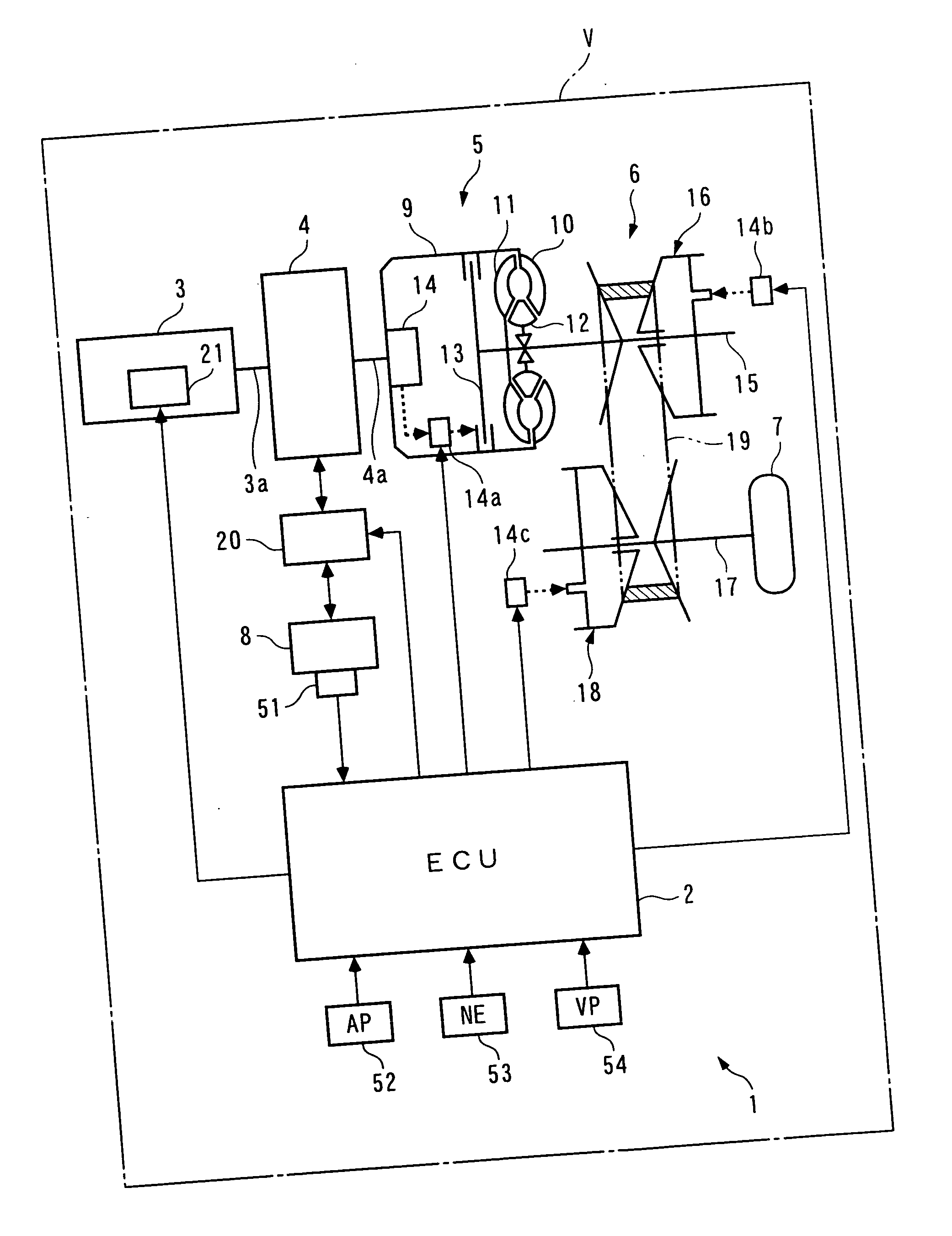
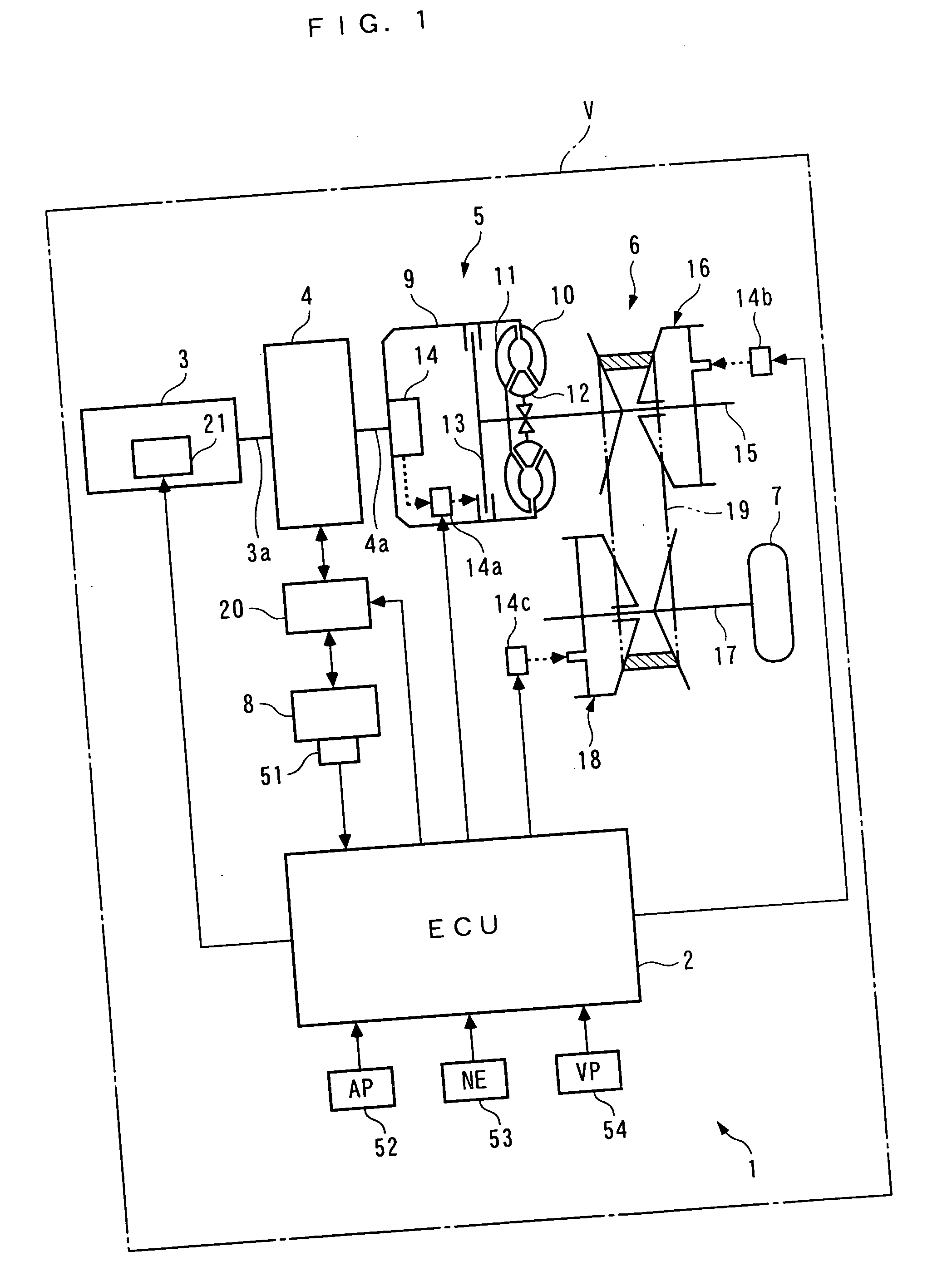
[0034] The invention will now be described in detail with reference to the drawings showing a vehicle (hybrid vehicle) to which is applied a control system 1 according to a preferred embodiment of the present invention.

[0035] The vehicle V is equipped with an internal combustion engine (hereinafter referred to as “the engine”) 3 and an electric motor 4, and is operated while switching a driven mode thereof between an engine-driven mode in which the vehicle V is driven by the engine 3 and a motor-driven mode in which the vehicle V is driven by the electric motor 4. The engine 3 has a crankshaft 3a thereof directly connected to an output shaft 4a of the electric motor 4, and the crankshaft 3a is connected to driving wheels 7 of the vehicle 4 via the output shaft 4a of the electric motor 4, a torque converter 5, a continuously variable transmission 6, and so forth.

[0036] The electric motor 4 is connected to a battery 8 as a drive source via a power drive unit (hereinafter referred to...


PUM


Abstract

A control system for a hybrid vehicle, which enables the hybrid vehicle to optimally selectively use driven modes to attain excellent fuel economy and thereby make it possible to improve fuel economy. The hybrid vehicle is operated in an engine-driven mode or a motor-driven mode, and recovers electric energy for driving an electric motor, using the output from the engine. The control system calculates a driving fuel consumption amount of the engine required for driving the hybrid vehicle in the engine-driven mode and a recovering fuel consumption amount of the engine required for recovering electric energy to be consumed when the hybrid vehicle is driven in the motor-driven mode, and sets the driven mode to the motor-driven mode when the recovering fuel consumption amount is smaller than the driving fuel consumption amount, and to the engine-driven mode when the former is larger than the latter.

Description

BACKGROUND OF THE INVENTION [0001] 1. Field of the Invention [0002] The present invention relates to a control system for a hybrid vehicle that is driven by an internal combustion engine and an electric motor, and is capable of recovering electric energy for driving the electric motor, using the output from the engine. [0003] 2. Description of the Related Art [0004] Conventionally, a control system of this kind has been proposed e.g. in Japanese Laid-Open Patent Publication (Kokai) No. 2002-242718. This control system is configured such that the vehicle is driven by the engine during normal operation of the vehicle, such as cruising, and when the degree of increase in the throttle valve opening is large, the vehicle is driven not only by the engine but also by the electric motor n an auxiliary manner so as to ensure the feeling of acceleration. Further, depending on the operating conditions of the engine, the electric motor operates as a generator to generate electric energy using t...

Claims


Application Information

Patent Timeline
Patent Type & Authority Applications(United States)
IPC IPC(8): B60W20/00B60K6/485B60K6/543B60L50/16B60W10/06B60W10/08F01L1/18F01L13/00F02D13/02G06F17/00
CPCB60K6/485Y02T10/142B60W10/06B60W10/08B60W20/00F01L1/181F01L13/0036F01L2105/00F01L2800/00F02D13/0234F02D13/0257F02D13/0269F02D2041/001F02D2200/0625Y02T10/52Y02T10/56Y02T10/6226Y02T10/6286Y02T10/18B60K6/543B60L50/16F01L2305/00Y02T10/12Y02T10/40Y02T10/62Y02T10/7072B60W20/15Y02T10/70
Inventor KURODA, SHIGETAKAKAMIMURA, TAKASHIMURAKAMI, HIROSHIOHTSU, AKIHITOASAMI, KIYOSHITSUJI, NAOKI
Owner HONDA MOTOR CO LTD
Learn More