Warming device

Inactive Publication Date: 2005-02-10
KAO CORP
View PDF7 Cites 40 Cited by
  • Summary
  • Abstract
  • Description
  • Claims
  • Application Information

AI Technical Summary

Benefits of technology

[0005] An object of the present invention is to provide a warming device which is thin, f

Problems solved by technology

Furthermore, since the thick heat generating elements being attached to the base sheet li

Method used


Image

  • Warming device
  • Warming device
  • Warming device

Examples


first embodiment

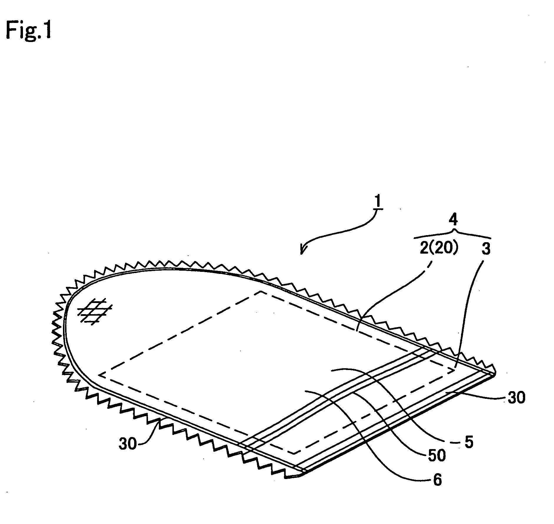
[0016]FIGS. 1 and 2 show the present invention, in which the warming device is shaped into a mitten. In these figures numeral 1 indicates the warming device.

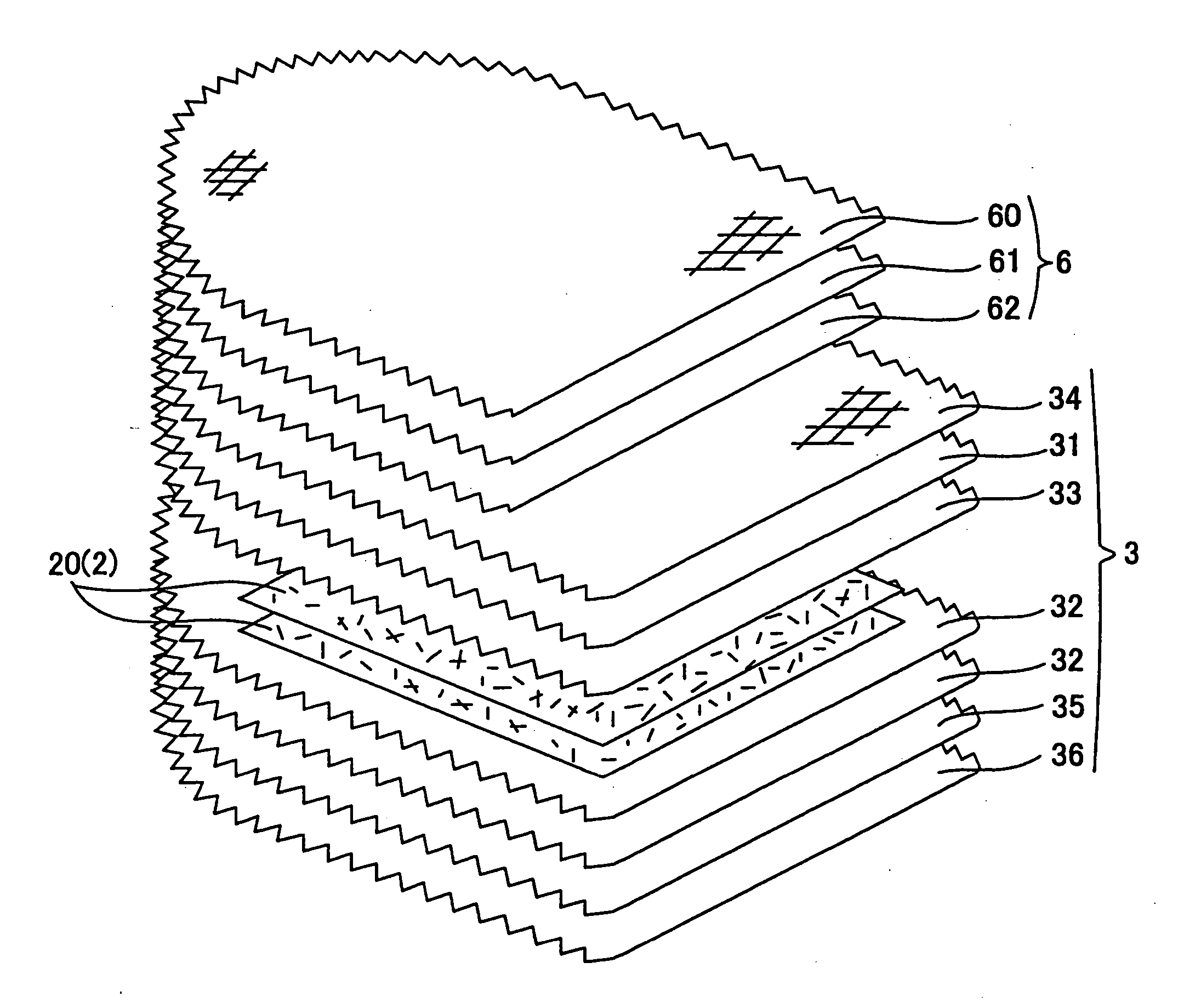
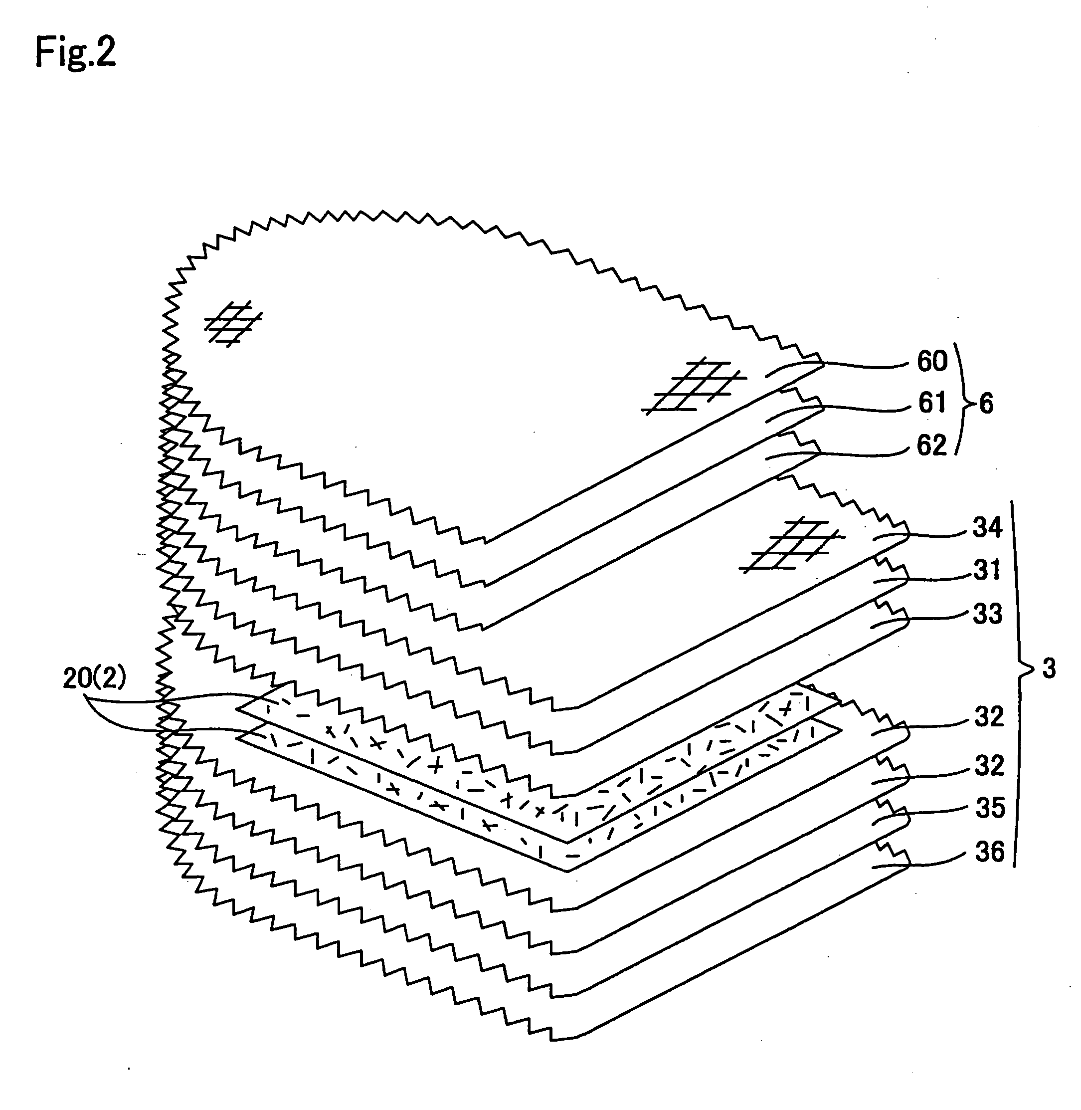
[0017] As illustrated in FIG. 1, the warming device 1 consists essentially of a heat generating main body 4 which comprises a heat generating element 2 and an air-permeable holding member 3 having the heat generating element 2 enclosed therein. The warming device 1 has a receiving part 5 for receiving a part of a body being inserted. The warming device 1 has an receiving part-forming member 6 bonded to the upper side of the heat generating main body 4 to form the receiving part 5 having an insertion opening 50 on the outer side of the heat generating main body 4.

[0018] The heat generating element 2 is composed of a sheet 20 which is prepared by papermaking and contains an oxidizable metal, a moisture-retaining agent, and a fibrous material. A sheet 20 which does not contain an electrolyte component is called a heat generating i...

fourth embodiment

[0119] In using the warming device 1′ of the fourth embodiment, it is put on the head as shown in FIG. 7, and the head is warmed by the heat generated on oxidation of the oxidizable metal of the heat generating element 2.

[0120] The warming device 1′ of the fourth embodiment is thin, flexible, and conformable to the shape of the head. It is suitable as a warming cap in, for example, hair care applications in perming, hair dyeing, hair treatment, and the like.

[0121] The present invention is not construed as being limited to the above-described embodiments, and various changes and modifications can be made therein without departing from the spirit and scope thereof.

[0122] The following modifications are included under the scope of the present invention. The layer structures of the heat generating element, the holding member, and the receiving part-forming member are subject to variation according to the purpose. For example, the heat generating main body may be adapted to dissipate w...


PUM


Abstract

A warming device consisting essentially of a heat generating main body comprising a heat generating element and an air-permeable holding member having the heat generating element enclosed therein. The warming device has a receiving part for receiving a part of a body being inserted. The heat generating element comprises a sheet which contains an oxidizable metal, a moisture-retaining agent, and a fibrous material and is prepared by papermaking.

Description

BACKGROUND OF THE INVENTION [0001] The present invention relates to a warming device utilizing heat generation accompanying oxidation of an oxidizable metal with oxygen in air. [0002] Known techniques pertinent to warming devices utilizing heat generation accompanying oxidation of an oxidizable metal powder with air oxygen include the warming tool described in JP-A-2003-332. [0003] The warming tool disclosed comprises a cap-shaped base sheet which is put on a head and a plurality of heat generating elements attached to the base sheet, the heat generating elements each comprising an air permeable flat bag containing heat generating powder. [0004] Because the heat generating elements used in this warming tool are thick, a thinner warming device has been desired. Because the heat generating elements lose flexibility as the heat generating powder becomes harder, a warming device having excellent in flexibility and thereby providing a good fit has been desired. Furthermore, since the thi...

Claims


Application Information

Patent Timeline
IPC IPC(8): A61F7/00A45D8/40A61F7/02A61F7/03A61F7/08F24V30/00
CPCA61F7/034A61F2007/0062A61F2007/0036A61F2007/0008
Inventor KUMAMOTO, YOSHIAKIISHIKAWA, MASATAKAORII, TAKAOHALL, CHRISTINELYNCH, JILL KATHLEEN
Owner KAO CORP
Why Eureka
Try Eureka