Rechargeable batteries

a rechargeable battery technology, applied in the charging circuit of different batteries, electric vehicles, charging circuits, etc., can solve the problems of affecting the safety of electric vehicles, affecting the operation of electric vehicles, and requiring care with these batteries

Inactive Publication Date: 2005-02-10
MORGAN RICHARD
View PDF10 Cites 41 Cited by
  • Summary
  • Abstract
  • Description
  • Claims
  • Application Information

AI Technical Summary

Benefits of technology

The individual cells or groups of cells that are arranged to discharge in parallel to each other can be substantially simultaneously recharged by being recharged independently of each other leading to great savings in recharging time.
A double coating of the nylon is suitably applied to both the inner and outer surfaces of the casing. The thermal insulation is highly effective and may be further enhanced by the use of foam-in-place resin such as polyurethane resin that is introduced into the battery within the casing to foam and cure and fill out voids within the casing.
The sophistication of the system enables multiple batteries not only to be independently polled for information but also mapped and monitored from a centralised computer-based facility with simple geographical map screen displays identifying the location of each unit with a respective on-screen marker pin and information on each being obtainable at the touch of a button. The ability of the unit to communicate on remote demand or in response to local triggering enables power conservation, by drawing power only when required.

Problems solved by technology

Although Ni-MH batteries have greater capacity per unit size and weight and are more ecologically acceptable, care must still be taken with these batteries since they are prone to risk of oxygen or hydrogen build up.
Mistreatment of the battery may, however, lead to build up of hydrogen.
Build up of either of these gases can represent a significant hazard.
A relatively slower rate of charging than Ni-Cad batteries and lesser high drain capability represent further limitations of NiMH batteries and neither NiCad nor NiMH batteries exist with high current yield (e.g. 64 Amps) or which can be rapidly charged to such a level (e.g. in as little as four hours).
This severely limits the usefulness of these batteries.
Furthermore these batteries are rendered useless at markedly sub-zero ambient temperatures.
In some cases the installations involved may be many miles, even hundreds or more miles remote from the nearest technicians and the problem of maintaining an up to date knowledge of the status and performance of the batteries can be acute.

Method used


Image

  • Rechargeable batteries
  • Rechargeable batteries

Examples


Embodiment Construction

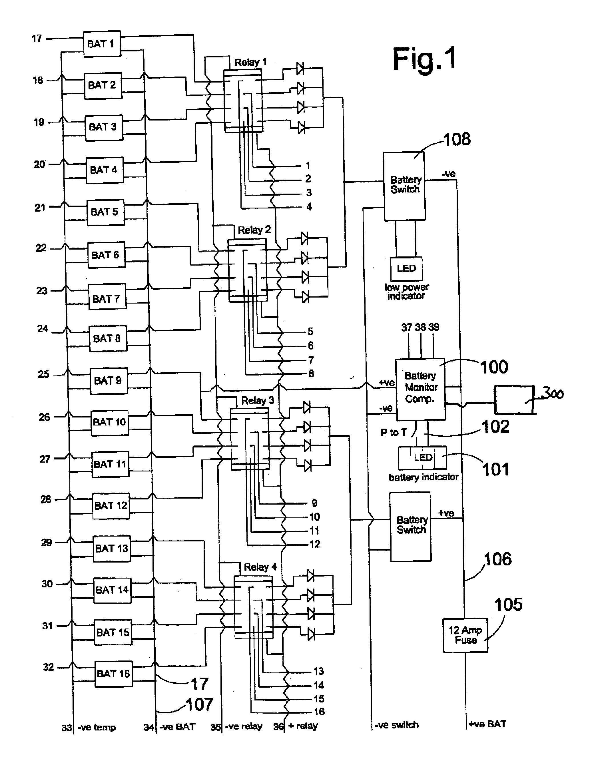
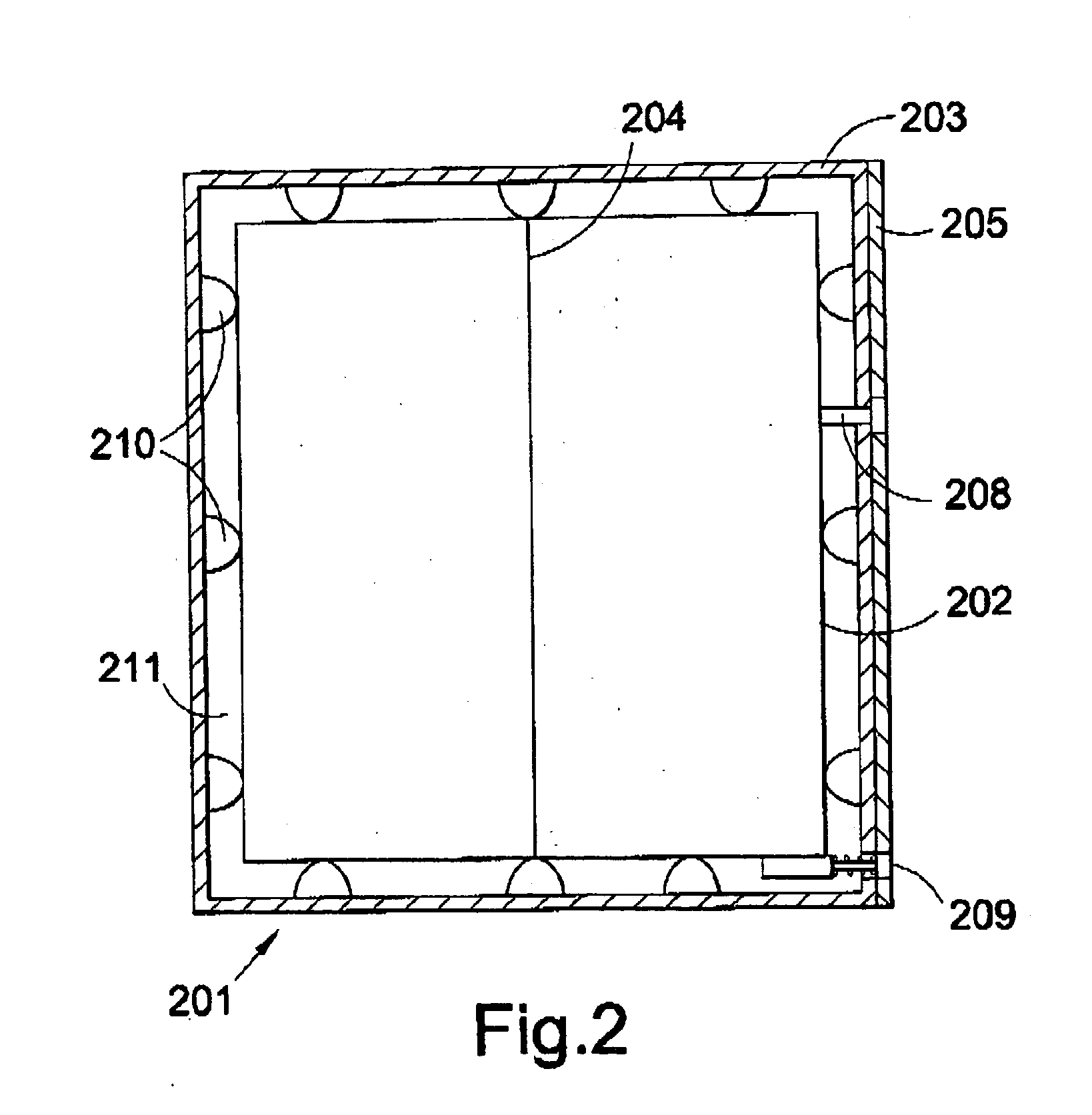
Referring to FIG. 1, sixteen Ni-MH battery packs BAT 1-BAT 16 each pack having ten cells in series and storing 4 Ah of charge are positioned inside the battery casing 201 (FIG. 2).

Each battery pack BAT 1-BAT 16 contains its own protection devices and allows an in-built redundancy capability down to the last remaining pack.

The casing 201 for the rechargeable battery comprises an inner shell 202, an outer shell 203 made from 2 mm rigidised aluminium, in the shape of a box with a removable lid. All corners and joints at least of the outer shell 203 are welded to improve structural strength and to prevent water from entering the rechargeable battery unit.

Both the inner and outer shells 202, 203 are covered with a double coating of ‘Rilsan Nylon’ giving an extremely hard wearing surface as well as reducing internal condensation to a minimum.

The inner shell 202 is suitably divided into two compartments via a bulk-head, 204 one for the battery packs and the other for the “electron...


PUM


Abstract

An improved rechargeable battery which comprises: a plurality of battery cells connected together to discharge in parallel, each of the cells, or each group or groups of the cells having its own respective recharging input; and an electrical switching circuit to switch a number of the battery cells or groups of cells to connect to their respective recharging input for recharging each cell or group of cells individually.

Description

FIELD OF THE INVENTION The present invention concerns rechargeable batteries. BACKGROUND TO THE INVENTION Major advances have been made in recent years in computing and telecommunications electronic hardware, and in part because of the heavy investment in research and development in these high technology areas, advancements are now being pursued in the field of battery design. The compelling objectives of increasing battery capacity while reducing their volume and weight and meeting ecological concerns are now being achieved inter alia through the introduction of nickel metal hydride (Ni-MH) batteries. Such batteries offer higher energy densities than Ni-Cad batteries enabling downscaling of the batteries while enhancing the run time of the batteries. A Ni-MH battery has approximately double the capacity of an equivalent sized Ni-Cad battery. Although Ni-MH batteries have greater capacity per unit size and weight and are more ecologically acceptable, care must still be taken wit...

Claims


Application Information

Patent Timeline
Patent Type & Authority Applications(United States)
IPC IPC(8): H02J7/00
CPCH02J7/0047H02J7/0018H02J7/0048
Inventor MORGAN, RICHARD
Owner MORGAN RICHARD
Why Eureka
Try Eureka