Method and system for measuring and controlling an OLED display element for improved lifetime and light output

a technology of oled display element and measurement method, which is applied in the field of modulear organic lightemitting diode (oled) display, can solve the problems of lcds not meeting the high resolution and speed requirements of lcds fail to provide the bright, high light output, and large viewing angle that the large-screen display market demands, and the use of oled technology in large-screen display applications such as outdoor or indoor stadium displays, large marketing

Inactive Publication Date: 2005-02-10
BARCO NV
View PDF8 Cites 318 Cited by
  • Summary
  • Abstract
  • Description
  • Claims
  • Application Information

AI Technical Summary

Benefits of technology

The present invention provides an OLED display tile that monitors and records the factors that contribute to its aging and compensates for them. In accordance with an aspect of the present invention an OLED display or display tile is provided that can measure an environmental factor which affects aging, especially an environmental temperature. In addition, other factors which affect aging may be measured such as ON time, and various other factors responsible for aging. The disclosed devices can adjust the OLED voltage source and drive current appropriately to maintain consistent color and uniform illumination across the entire display at levels that minimize aging. In addition it is preferred that the disclosed OLED display or display tile regulates its cooling to prolong display lifetime.
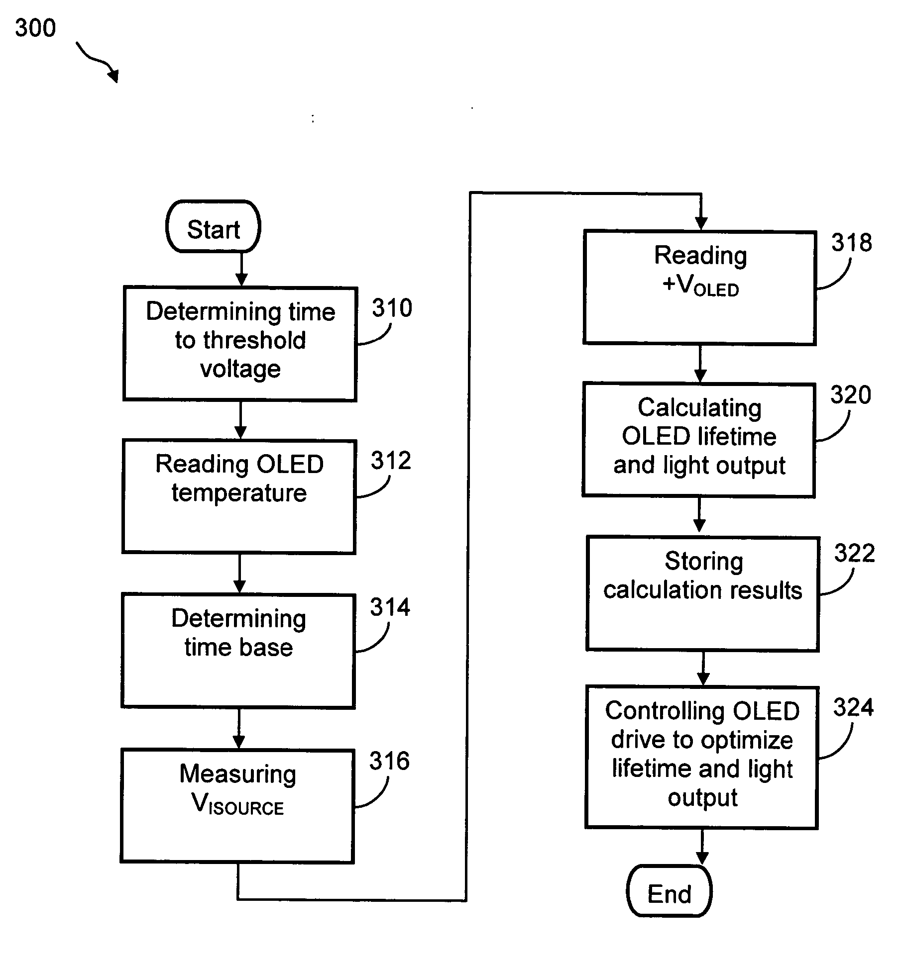
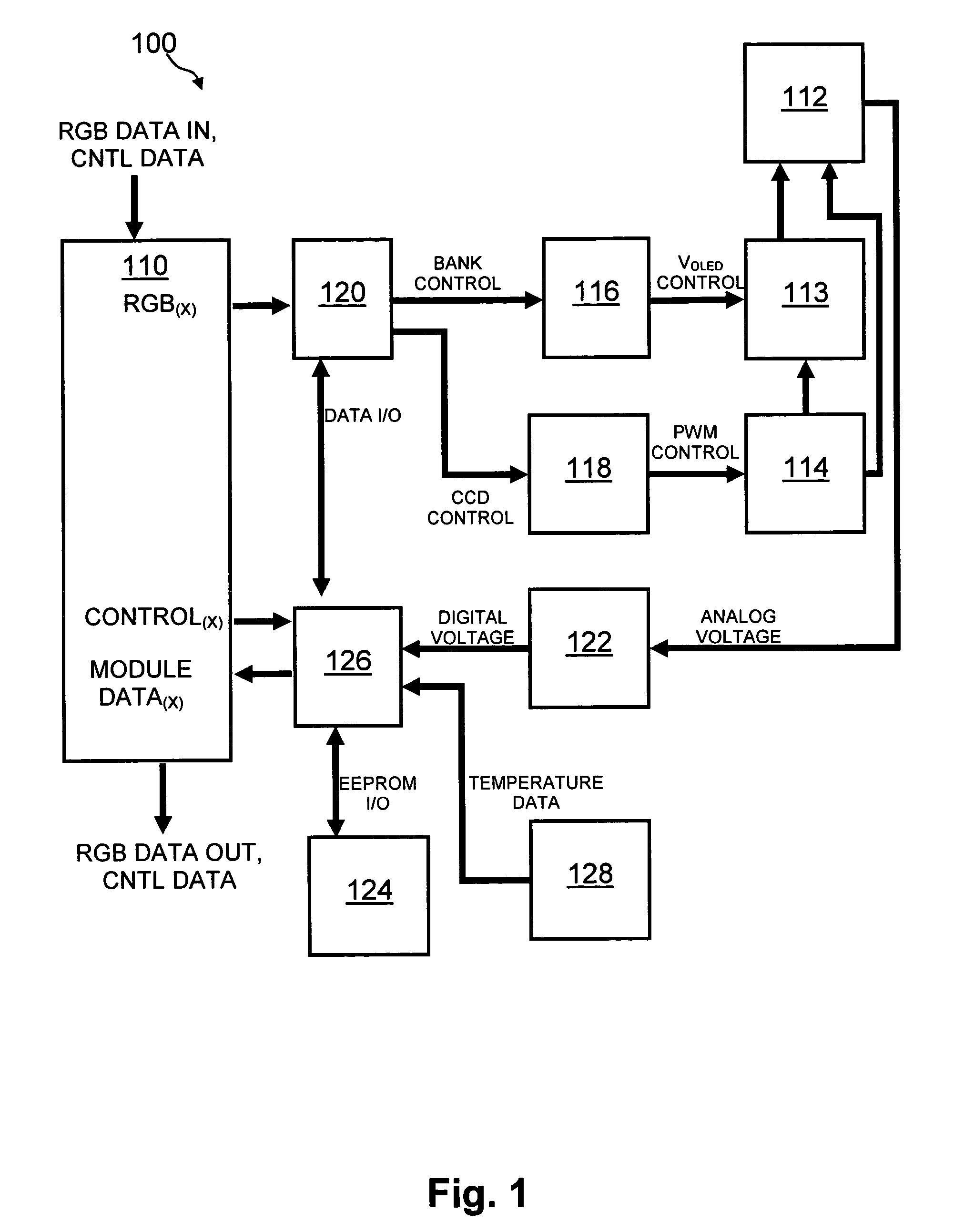
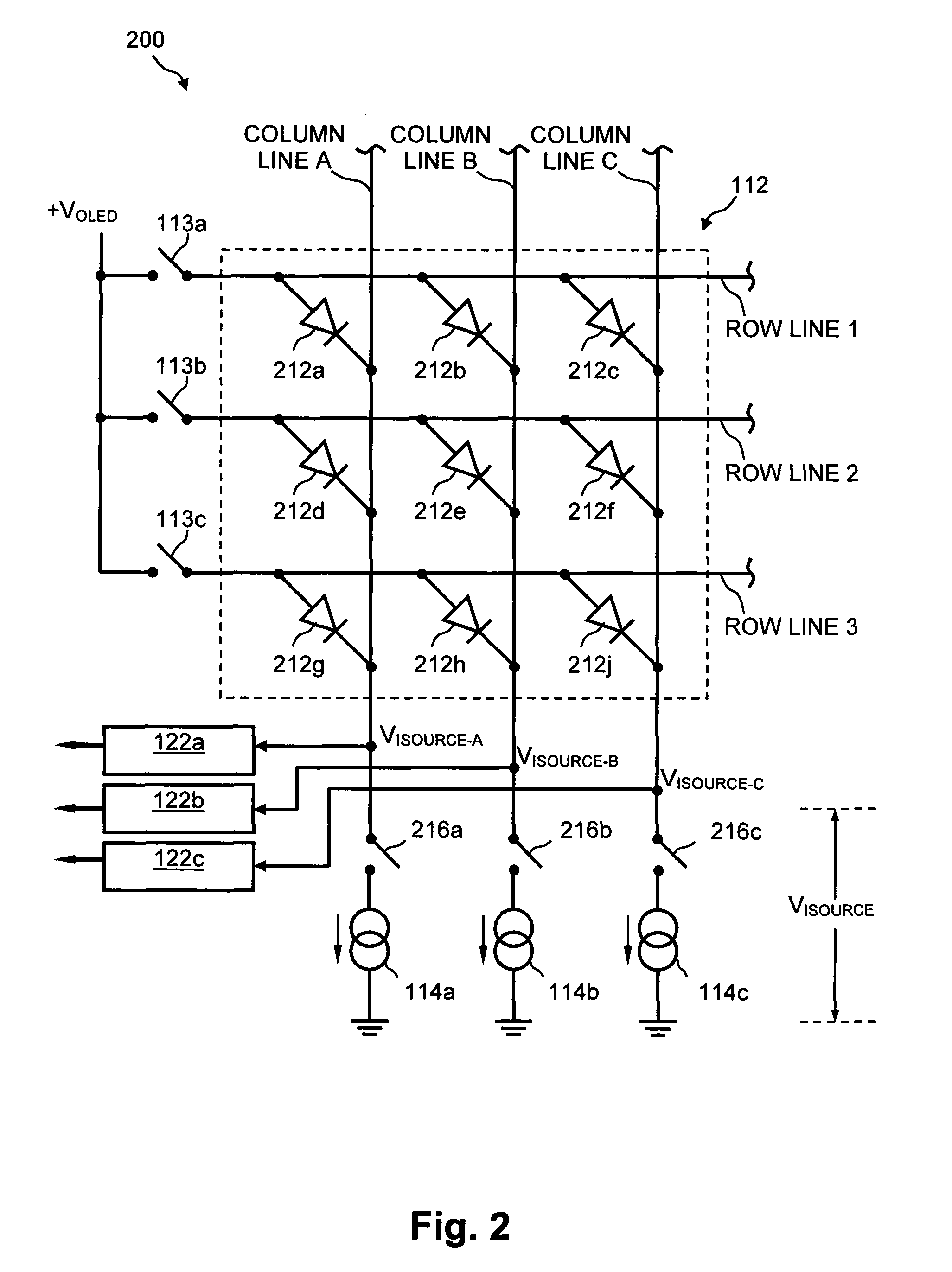
The present invention relates to a system for and a method of optimizing lifetime of an OLED display element, for possible use in a tiled display, while maintaining light output. It compensates the OLED drive parameters such as supply voltage and / or on-time of the operating current based on at least one environmental factor which affects aging and on at least one operating factor which determines the brightness of an OLED display element. The environmental factor is preferably one related to the operating temperature of the display and / or each display element of the OLED display. Such an environmental factor can be the ambient temperature. From the known ambient temperature plus the drive current history of each pixel, the actual operating temperature can be estimated. For example, an analytical model for an OLED display may be constructed which allows estimation of the temperature based on the ambient temperature and an estimate of the ON-current and the known cooling characteristics. The ON-current can be estimated from the input video signal taking into account the properties of the OLED display and the factors affecting the translation of a video signal of a certain amplitude into the drive signal for OLED display elements. The operating factor may be, for example, the voltage across the current driver. This can e.g. be used to determine the threshold voltage or the normal operating voltage of the OLED pixel or to determine a change in time duration required for a voltage across the OLED pixel to attain its threshold voltage or to attain its normal operating voltage. The measured temperature and the measured voltage across the current driver for each OLED pixel may be stored in a memory device. Furthermore or alternatively the system may optimize the pre-charging of the OLEDs to optimize the light output. The measured or estimated temperature may also be used to regulate the working temperature of the OLED, possibly by adapting cooling, so as to improve the lifetime of the OLED display characteristics, e.g. in a tiled display by reducing temperature differences between different tiles. The intensity and contrast of the display illumination may be set within predefined limits to reduce aging.
Intensity and contrast of OLED pixels may be set within predefined limits to reduce aging of the OLED display element.
The OLED display element according to the present invention may furthermore comprise means for reducing temperature differences over two different OLED display tiles.
The OLED display element may furthermore comprise means for setting intensity and contrast of OLED pixels within predefined limits to reduce aging of the OLED display element.

Problems solved by technology

To date, the use of light-emitting arrays or displays has been largely limited to small-screen applications such as those mentioned above.
For example, LCDs fail to provide the bright, high light output, larger viewing angles, and high resolution and speed requirements that the large-screen display market demands.
However, the use of OLED technology in large-screen display applications, such as outdoor or indoor stadium displays, large marketing advertisement displays, and mass-public informational displays, is only beginning to emerge.
Several technical challenges exist relating to the use of OLED technology in large-screen applications.
Thus, when the light output is no longer suitable, the entire display is replaced.
However, for large-screen applications, where the display may consist of a set of tiled OLED display panels, there is the possibility that one OLED display will age at a faster rate than another.
In addition, age differences in the overall display may exist due to replacement of an older tile with a newer tile.
Tiles may be replaced when a module is damaged or found to be defective.
The result of using the display's modularity to replace individual tiles is non-uniformity of the overall display, as the light output of newer replacements may be inconsistent with older existing OLED modules.
Although the compensation techniques described in the '587 and '732 patent applications provide a satisfactory means of compensation for many OLED applications, it does not adequately address the concerns of a display composed of many discrete tiles of various ages that are subjected to different aging conditions.

Method used


Image

  • Method and system for measuring and controlling an OLED display element for improved lifetime and light output
  • Method and system for measuring and controlling an OLED display element for improved lifetime and light output
  • Method and system for measuring and controlling an OLED display element for improved lifetime and light output

Examples


Embodiment Construction

The present invention will be described with respect to particular embodiments and with reference to certain drawings, but the invention is not limited thereto but only by the claims. The drawings described are only schematic and are non-limiting. In the drawings, the size of some of the elements may be exaggerated and not drawn on scale for illustrative purposes.

The present invention will mainly be described with reference to a single display but the present invention is not limited thereto. For instance, the display may be extendable, e.g. via tiling, to form larger arrays. Hence, the present invention may also include assemblies of pixel arrays, e.g. they may be tiled displays and may comprise modules made up of tiled arrays which are themselves tiled into supermodules. Thus, the word display relates to a set of addressable pixels in an array or in groups of arrays. Several display units or “tiles” may be located adjacent to each other to form a larger display, i.e. multiple d...


PUM


Abstract

A method of optimizing lifetime of an OLED display element and an OLED display element with optimized lifetime for possible use in a tiled display, while maintaining light output are described. It compensates an OLED operating parameter such as supply voltage and / or on-time of the operating current based on at least one environmental factor which affects aging and on at least one operating factor which is indicative of aging, e.g. by determining the brightness of an OLED display element. To optimize the light output, pre-charge of the aged OLED display elements can be optimized. The knowledge of the working temperature of OLED tiles may be used to regulate the cooling and thus the working temperature, thus improving the lifetime of the display. Furthermore the intensity and contrast of the display illumination may be set within predefined limits to reduce the aging.

Description

FIELD OF THE INVENTION The present invention relates to a modular organic light-emitting diode (OLED) display. In particular, this invention relates to a system for and method of measuring and controlling an OLED display element for improved lifetime and light output. BACKGROUND OF THE INVENTION OLED technology incorporates organic luminescent materials that, when sandwiched between electrodes and subjected to a DC electric current, produce intense light of a variety of colors. These OLED structures can be combined into the picture elements, or pixels, that comprise a display. OLEDs are also useful in a variety of applications as discrete light-emitting devices or as the active element of light-emitting arrays or displays, such as flat-panel displays in watches, telephones, laptop computers, pagers, cellular phones, calculators, and the like. To date, the use of light-emitting arrays or displays has been largely limited to small-screen applications such as those mentioned above. ...

Claims


Application Information

Patent Timeline
Patent Type & Authority Applications(United States)
IPC IPC(8): G09G3/32
CPCG09G2320/041G09G2320/0233G09G3/3216G09G2320/048
Inventor TANGHE, GINOTHIELEMANS, ROBBIEDEDENE, NELE
Owner BARCO NV
Why Eureka
Try Eureka