Optical pick-up apparatus

a pickup apparatus and optical technology, applied in the direction of disposing/mounting the head, data recording, instruments, etc., can solve the problems of high precision required for the rotation position adjustment the difficulty of arranging all three beams in the center of the same track, and the inability to adjust the rotation position of the diffraction grating with high precision, so as to simplify the assembly adjustment of the apparatus, reduce the effect of track offset and simple structur

Inactive Publication Date: 2005-02-10
SHARP KK
View PDF4 Cites 18 Cited by
  • Summary
  • Abstract
  • Description
  • Claims
  • Application Information

AI Technical Summary

Benefits of technology

[0030] An object of the invention is to provide an optical pick-up apparatus which can reduce track offset occurring in a

Problems solved by technology

However, in the conventional DPP method disclosed in JP-A 7-93764, there is a problem that accurate rotation adjustment of a relative position of the diffraction grating 4 with respect to the optical recording medium 10 must be carried out so as to dispose the SB1 and the SB2 to shift by {fraction (1/2)} track pitch exactly with respect to the MB.
However, since there is an isolation distance between the leading and following beams, it is difficult to arrange all of the three beams in the center of the same track when a track curvature exists, and a track offset occurs in the end.
Like this way, when a track curvature e

Method used


Image

  • Optical pick-up apparatus
  • Optical pick-up apparatus
  • Optical pick-up apparatus

Examples


first embodiment

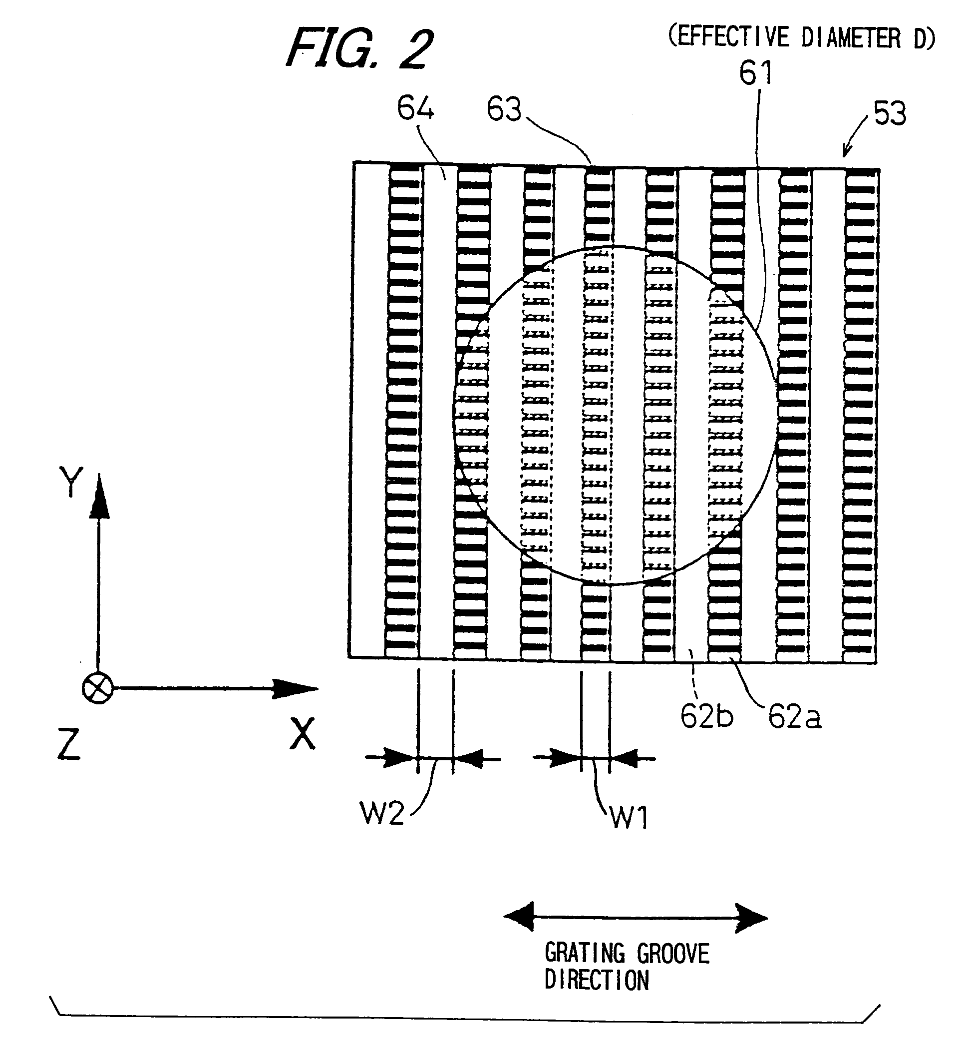
[0100] The diffraction grating 70 comprises two kinds of diffraction gratings 53a and 53b which has the same structure as the diffraction grating according to the invention. In other words, the diffraction grating 70 comprises the diffraction grating 53a and 53b formed so as to shift by {fraction (1 / 2)} taxo-pitch alternately (TP / 2) in X axis direction of the diffraction area 63 which provides a phase difference and the diffraction area 64 which provides no phase difference. The half-pitch (TP / 2) which is a shift amount is equal to the width W1 (=W2) of the diffraction area 63 which provides a phase difference and the diffraction area 64 which provides no phase difference. In the embodiment, two pieces each diffraction grating 53a and diffraction grating 53b, i.e., total 4 pieces are prepared, and these are structured so as to be arranged alternately adjacent to each other in Y axis direction. A height H which is a length of each diffraction grating 53a and 53b forming the diffracti...

third embodiment

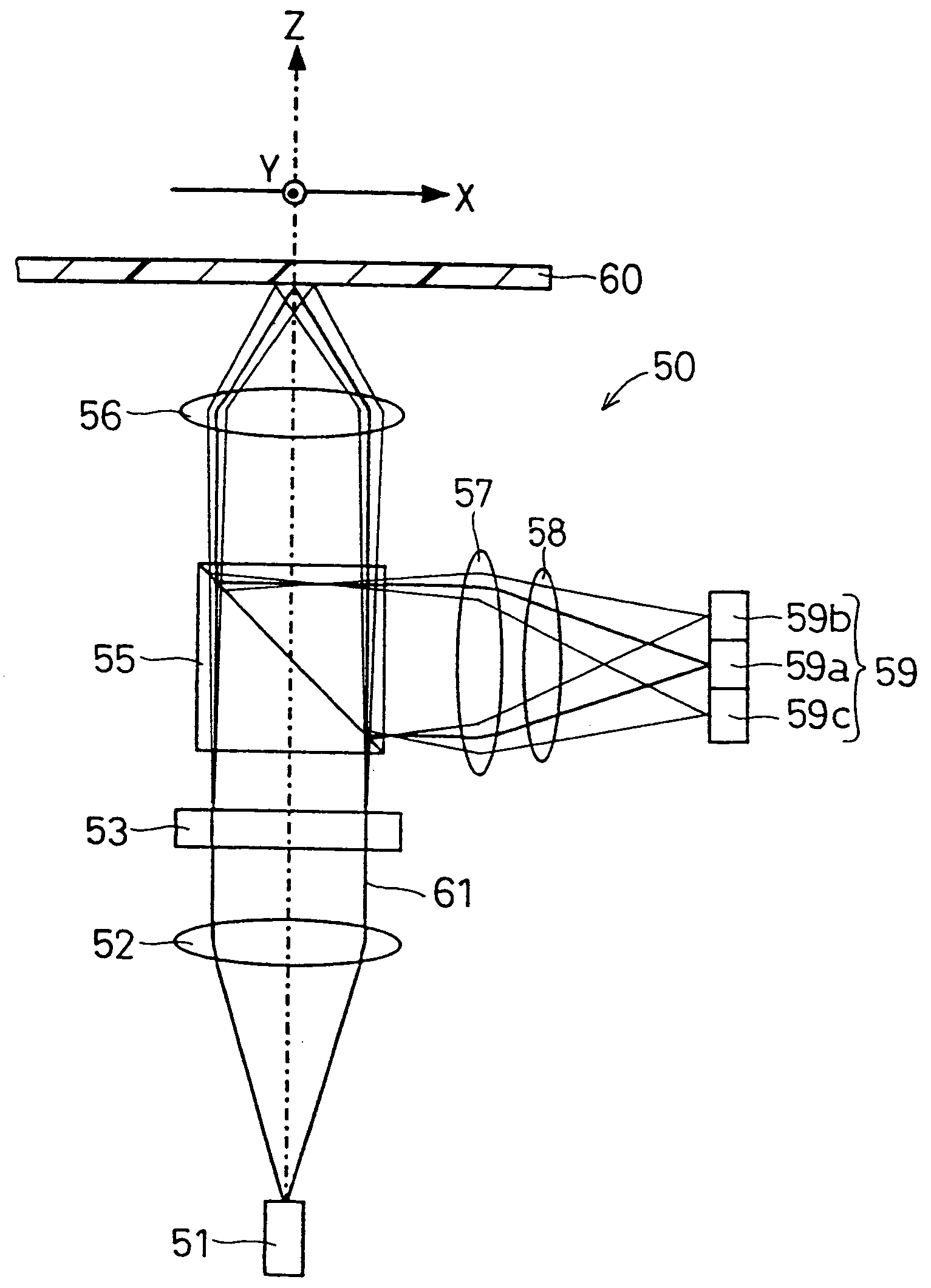
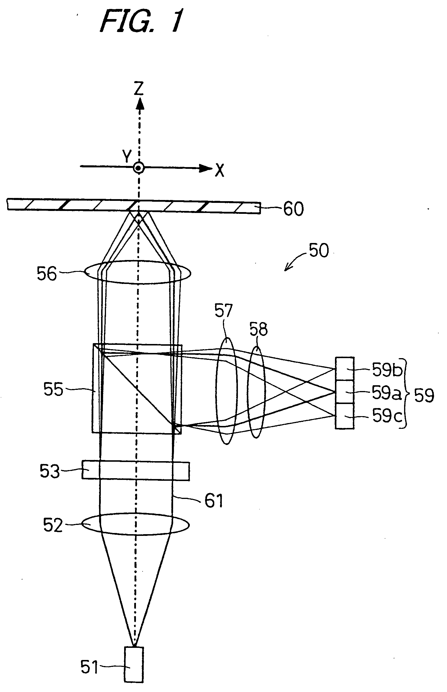
[0105]FIG. 9 is a simplified schematic diagram showing a structure of an optical pick-up apparatus 76 according to a forth embodiment of the invention. The optical pick-up apparatus 76 is similar to the optical pick-up apparatus 75 according to the invention. Accordingly, the same components as those described before will be denoted by the same reference numerals, and a repetition of a description thereof will be omitted. A remarkable point of the optical pick-up apparatus 76 is that the optical pick-up apparatus 76 includes a diffraction moving means 54 which moves the diffraction grating 53 in Z axis direction, i.e., a direction parallel with an axis of a light irradiated from the semiconductor laser 51.

[0106]FIG. 10 is a simplified perspective view showing a structure of the grating moving means 54 provided in the optical pick-up apparatus 76. FIG. 10 is a perspective view facing a light beam 61 irradiating surface of the diffraction grating 53 from the semiconductor laser 51 sid...


PUM


Abstract

An object of the invention is to provide a structure for suppressing occurrence of a track offset in a tracking control using DPP method, and simplified apparatus assembly adjustment. When a diffraction grating provided in an optical pick-up apparatus, diffracts light irradiated from a semiconductor laser at least into zero-order diffraction light and ± first-order diffraction light, disposed adjacent to diffraction area alternately in an extension direction of a grating groove, and an effective diameter of light beam with which the diffraction grating is irradiated is D, and a number of divisions into which the effective diameter D is divided is m (m is an integer of 3 or more), a width W1 and a width W2 are formed to meet W1=W2=D/m.

Description

BACKGROUND OF THE INVENTION [0001] 1. Field of the Invention [0002] The present invention relates to an optical pick-up apparatus which optically records information into an optical recording medium and / or reproduces information from an optical recording medium. [0003] 2. Description of the Related Art [0004] Optical disks like Compact Disc (CD), Digital Versatile Disc (DVD), and Mini Disc (MD), etc. are utilized as optical recording media in various fields such as audio video and computer, etc. In accordance with increasing demand of storage capacity, i.e. information volume to be recorded into above mentioned optical recording media, also getting along with narrower track pitch which is a track interval formed on the optical recording medium, information storing area has been expanding to nearly center inside of the optical recording medium. [0005] In an information reproducing apparatus using such an optical recording medium, information are recorded or reproduced by converging a...

Claims


Application Information

Patent Timeline
IPC IPC(8): G11B7/08G02B5/18G11B7/00G11B7/09G11B7/12G11B7/135G11B7/1353
CPCG11B7/0906G11B7/1353G11B7/094
Inventor HORIYAMA, MAKOTO
Owner SHARP KK
Why Eureka
Try Eureka