Master station of communication system and access control method

a communication system and master station technology, applied in the direction of data switching network, wireless commuication services, signalling characterisation, etc., can solve the problems of not allowing one communication system to maintain, the amount of signal attenuation in one communication system may substantially exceed the amount of signal attenuation, and the device may be unable to perform device communication in the system, so as to achieve the effect of avoiding interference between communication systems

Active Publication Date: 2005-02-10
PANASONIC CORP
View PDF3 Cites 54 Cited by
  • Summary
  • Abstract
  • Description
  • Claims
  • Application Information

AI Technical Summary

Benefits of technology

[0011] Therefore, an object of the present invention is to provide a master station and an access control method being capable of easily avoiding interference between communication systems while assuring QoS of a communication bandwidth of each communication system without performing transmission power control in a plurality of communication systems sharing the same channel.
[0020] As described above, based on the present invention, a communication bandwidth is divided into the following three periods: a beacon period, a first CSMA period, and a second CSMA period, and an allocation for the first CSMA period is determined based on information about a currentlyused communication bandwidth of each communication system. As a result, even if a plurality of communication systems share the same channel, it is possible to easily avoid interference between communication systems and assure QoS of a communication bandwidth of each communication system without performing transmission power control. Also, different access modes do not affect each other.

Problems solved by technology

However, in the case where the above-described communication system is a power line communication system, depending on the configuration of a device connected to a network, an amount of signal attenuation in one communication system may substantially exceed an amount of signal attenuation which interferes with the other communication systems due to the characteristics of a power line transmission path.
That is, in the case where patent document 1 or patent document 2 is applied to the power line communication system and interference between the communication systems is performed by power control, there is a possibility that, depending on the device configuration, some devices may be unable to perform device communication in the system due to reduced signal intensity.
The above-described conventional configuration does not allow one communication system to maintain the quality of communications performed therein by transmission power control while reducing interference with the other communication systems.
Thus, throughput of each communication system is substantially reduced due to the interference between the communication systems, and it is difficult to perform communication bandwidth control.
However, it is impossible to assure quality of service (QoS) of a communication bandwidth.

Method used


Image

  • Master station of communication system and access control method
  • Master station of communication system and access control method
  • Master station of communication system and access control method

Examples


first embodiment

[0046] (First Embodiment)

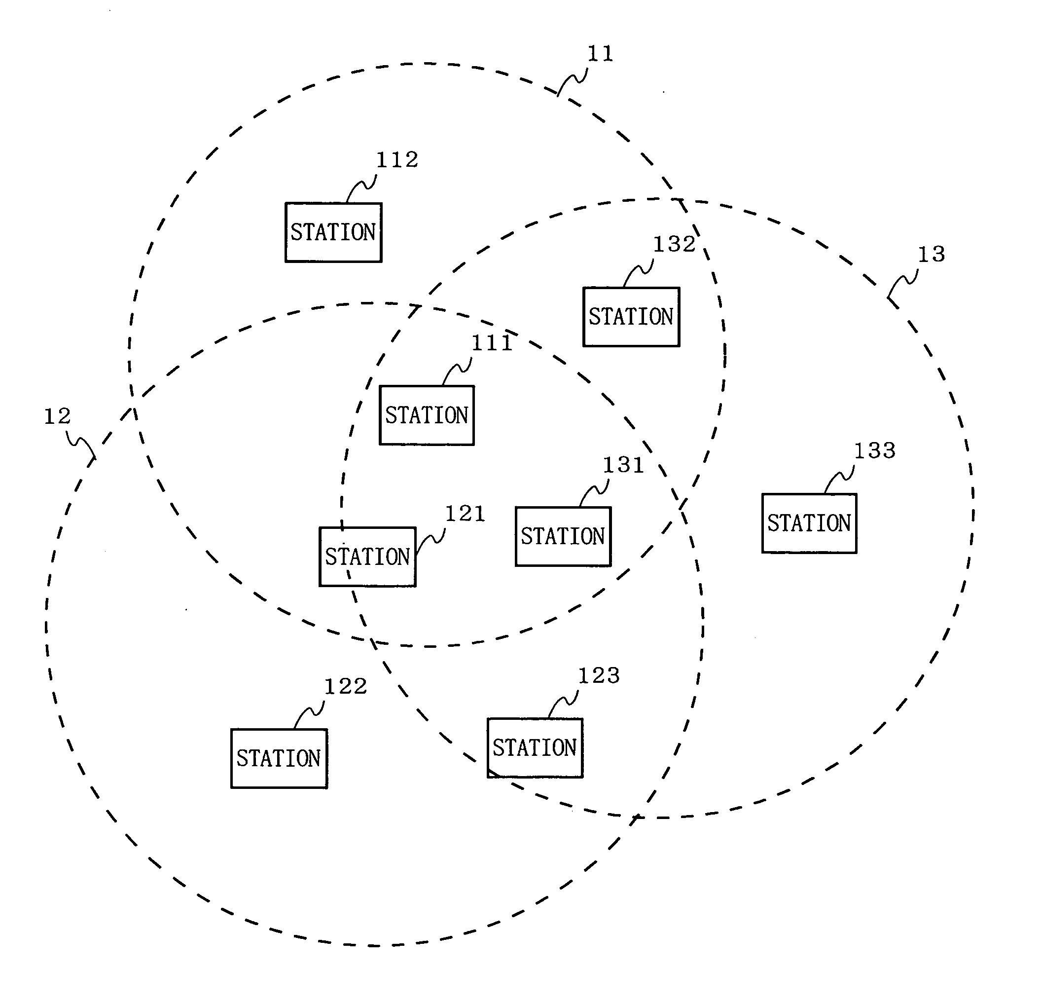
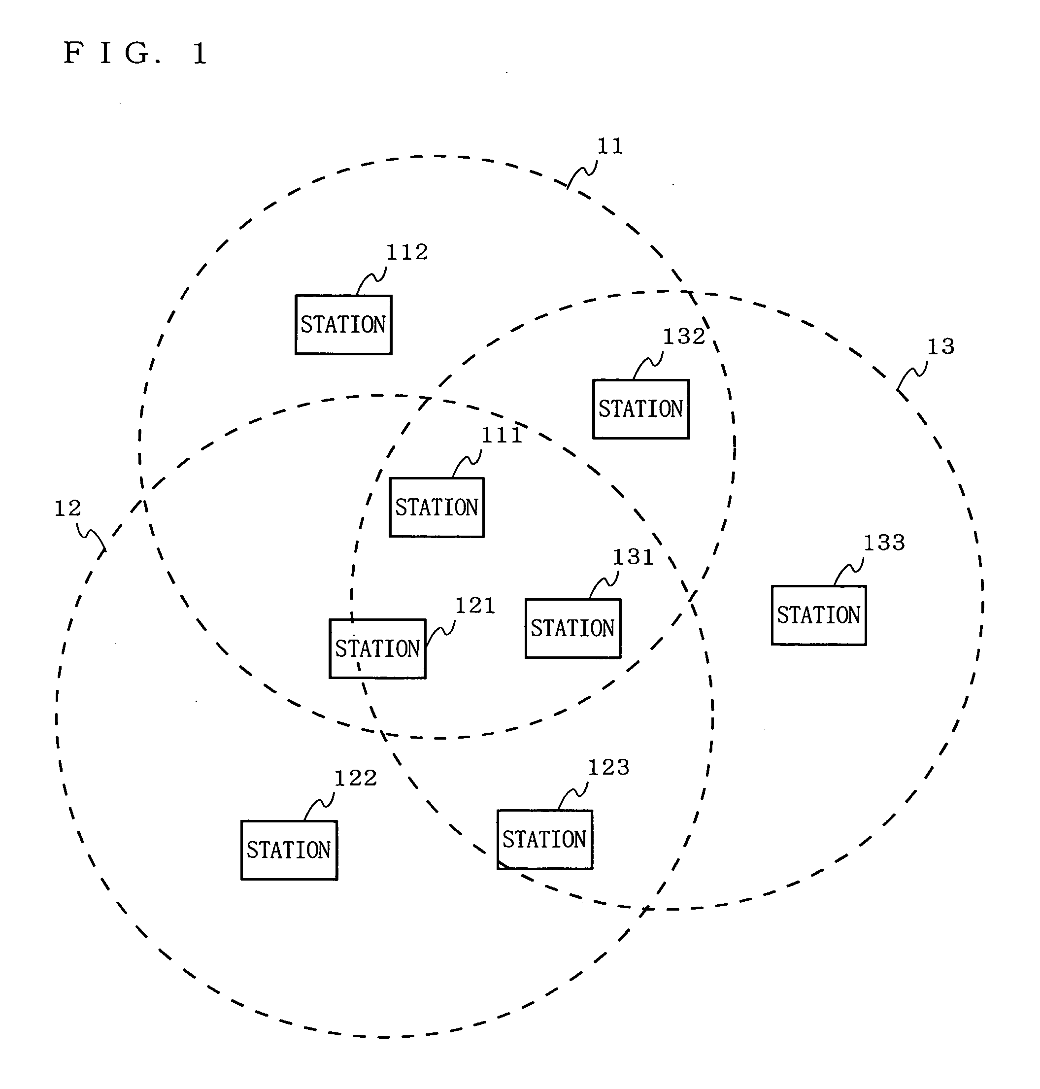
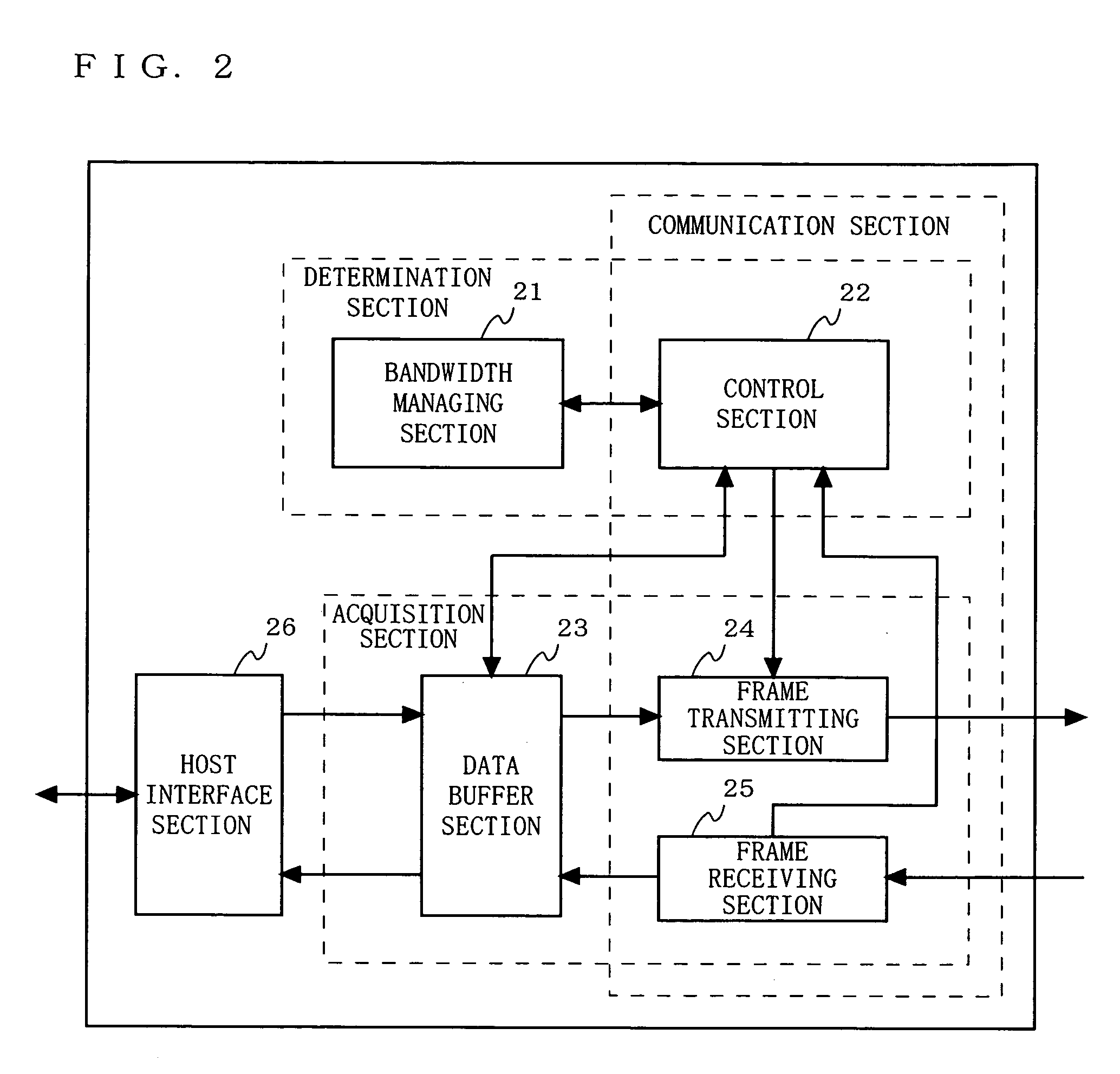
[0047]FIG. 4 is a timing chart for describing an access control method according to a first embodiment of the present invention. Note that, in the present embodiment, a case in which start times of the beacon periods are the same (i.e., start times of the beacon periods are previously synchronized) will be described. In order to synchronize start and end times of the beacon periods, a method which will be described in a third embodiment may be used, for example. Also, assume that information about a communication bandwidth used by a communication system is transmitted as information stored in a beacon packet. FIG. 5 is a flowchart for describing the access control method (bandwidth managing method) according to the first embodiment of the present invention.

[0048] As shown in FIG. 4, each of the control sections 22 included in the respective master stations 111, 121, and 131 performs a random back-off process within a beacon period for transmitting its own b...

second embodiment

[0059] (Second Embodiment)

[0060] In a second embodiment, with reference to FIGS. 10 to 14, a specific example of a case in which the access control method described in the first embodiment is applied to a power line communication system will be described. FIGS. 10 to 14 are illustrations showing a format of a beacon packet (beacon frame) used for power line communications for storing allocation information and announcing the information to the system.

[0061] Assume that TINF information included in VF (Variant Field) in frame control stores information about communication bandwidths T1 to Tn, which are necessary for assuring QoS and accepted by a plurality of master stations 1 ton (n is an arbitrary integer), respectively. Also, as shown in FIG. 14, schedule information SI included in a data body section of a beacon packet stores information about an allocated time of a beacon period, an allocated time AT of a Controlled-CSMA period, and an allocated time of a Normal-CSMA period. In...

third embodiment

[0070] (Third Embodiment)

[0071] In a third embodiment, a process for synchronizing start and end times of the beacon periods, the process being usable in combination with the access control method described in the first embodiment, will be described. FIG. 15 is a flowchart showing a procedure of an access control method according to the third embodiment of the present invention (master station side). FIG. 16 is a flowchart showing a procedure of an access control method according to the third embodiment of the present invention (slave station side).

[0072] Each master station individually determines whether or not a beacon packet is newly received (step S1501). In the case where the beacon packet is not received, the master station acquires a value of its own timer (step S1502). The master station determines whether or not the acquired timer value reaches a start time of a beacon period (step S1503). If a start time is not reached, a process is returned to step S1501. If a start tim...


PUM


Abstract

A communication bandwidth is divided into a beacon period in which all master stations compete for transmission of a beacon packet, a first carrier sense multiple access (CSMA) period in which only authorized specific stations are allowed to compete for access, and a second CSMA period in which all stations are allowed to compete for access. The master stations exchange information with each other about a communication bandwidth being used in the first CSMA period, thereby calculating a communication bandwidth which can be used by each communication system in the first CSMA period, based on the information.

Description

BACKGROUND OF THE INVENTION [0001] 1. Field of the Invention [0002] The present invention relates to a master station of a communication system and an access control method, and more particularly, relates to an access control method, which is used in a plurality of communication systems sharing the same channel, for preventing interference between the plurality of communication systems from occurring. [0003] 2. Description of the Background Art [0004] Conventionally, as a technique for reducing interference between a plurality of communication systems sharing the same channel, there exists an access control method for reducing the influence of interference signals by transmission power control. For example, there exists Japanese Laid-Open Patent Publication No. 2002-198834 (patent document 1), Japanese Laid-Open Patent Publication No. 2003-37556 (patent document 2), or Japanese Laid-Open Patent Publication No. 2001-53745 (patent document 3). [0005] Patent document 1 discloses a meth...

Claims


Application Information

Patent Timeline
Patent Type & Authority Applications(United States)
IPC IPC(8): H04L1/00H04L1/18H04L12/28H04W12/08H04W72/00H04W72/04H04W74/08H04W84/12
CPCH04L1/0026H04W74/0808H04W12/08H04L1/188Y04S40/20H04L12/28
Inventor OHMI, SHINICHIROYOSHIZAWA, KENSUKEYAMAGUCHI, TSUYOSHI
Owner PANASONIC CORP
Why Eureka
Try Eureka