
Suction muffler for a reciprocating hermetic compressor

a reciprocating hermetic compressor and suction muffler technology, which is applied in the direction of positive displacement liquid engines, pumping, room acoustics, etc., can solve the problems of reducing the and reducing the efficiency of the compressor. , to achieve the effect of fast and efficient equalization of pressure and causing the loss of volumetric efficiency of the compressor

Inactive Publication Date: 2005-02-10
EMBRACO IND DE COMPRESSORES E SOLUCOES EM REFRIGERACAO LTDA
View PDF11 Cites 18 Cited by
  • Summary
  • Abstract
  • Description
  • Claims
  • Application Information

AI Technical Summary

Benefits of technology

[0011] It is an object of the present invention to provide a suction muffler for a reciprocating hermetic compressor with direct suction, which does not present the inconveniences of the known prior art solutions, producing a fast and efficient equalization of the pressures existing inside the shell and inside the suction muffler, without submitting the elements of the direct suction to undesirable efforts and without causing loss in the volumetric efficiency of the compressor.
[0012] It is another object of the present invention to provide a suction muffler as mentioned above, which produces a better attenuation of the noises produced by the gas pulses inside the suction muffler.
[0013] It is a further object to provide a suction muffler, which, besides the above characteristics, allows for a better fixation of the connector to the gas inlet thereof. SUMMARY OF THE INVENTION
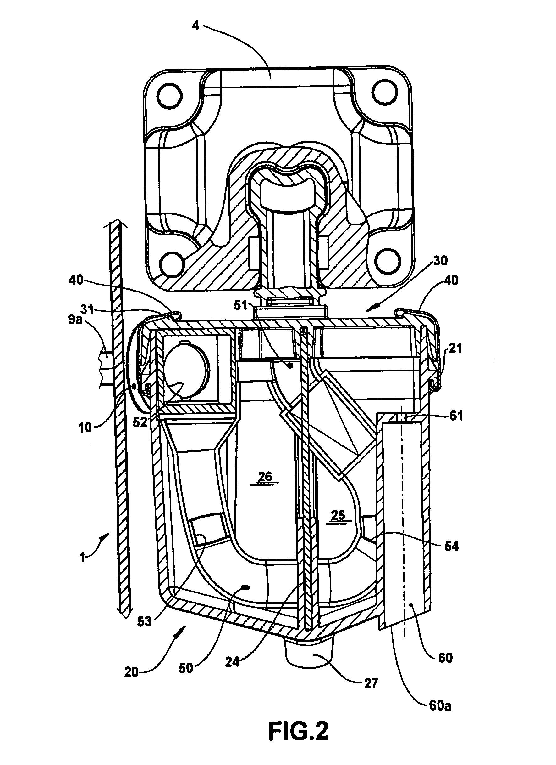
[0014] These and other objects are achieved by a suction muffler for a reciprocating hermetic compressor mounted inside a hermetic shell, said suction muffler comprising a hollow body that defines at least one acoustic chamber and that is provided with a gas inlet connected to a suction line by means of a flexible connector, and with a gas outlet connected to a suction valve of the compressor, said suction muffler comprising an equalizing chamber, which is provided, on one side, with an opening to the inside of the hermetic chamber and, on the other side, with a fluid communication with the acoustic chamber, said equalizing chamber and said fluid communication being dimensioned so as to minimize, simultaneously, the transfer of acoustic energy to the cavity of the shell, the mixture of said gas with that contained inside the hermetic shell, and the pressure differential between the inside of the latter and the suction line, upon operation of the compressor after a stop period.

Problems solved by technology

On the other hand, the suction muffler represents a load loss to the gas flow being drained.
However, this known construction presents the inconvenience of not allowing the refrigeration system to rapidly and adequately return to the pressure levels of the normal working regimen of the compressor, when the latter is driven after a stop period in which the pressure inside the shell is raised to a value of equilibrium with the suction and discharge sides of the compressor.
When the compressor is re-started, the pressure inside the suction muffler and inside the flexible connector is suddenly reduced, originating a pressure differential that is greater than the stop pressure inside the compressor shell, causing a certain collapse of the flexible connector and the compressor assembly tilts toward the shell, compressing the flexible connector and submitting it to undesirable efforts as long as the strong pressure unbalance condition lasts between the interior of the shell and the interior of the suction muffler.
Since the latter is constructed, in case of the direct suction, to be relatively hermetically coupled to the inlet of the suction muffler and to the shell, the pressure inside the latter remains high in relation to the interior of the suction muffler for a long period, during which the flexible connector remains resiliently deformed and inadequately subjected to undesirable efforts that tend to damage it or displace it from its operative position.

Method used


Image

  • Suction muffler for a reciprocating hermetic compressor
  • Suction muffler for a reciprocating hermetic compressor
  • Suction muffler for a reciprocating hermetic compressor

Examples


Embodiment Construction

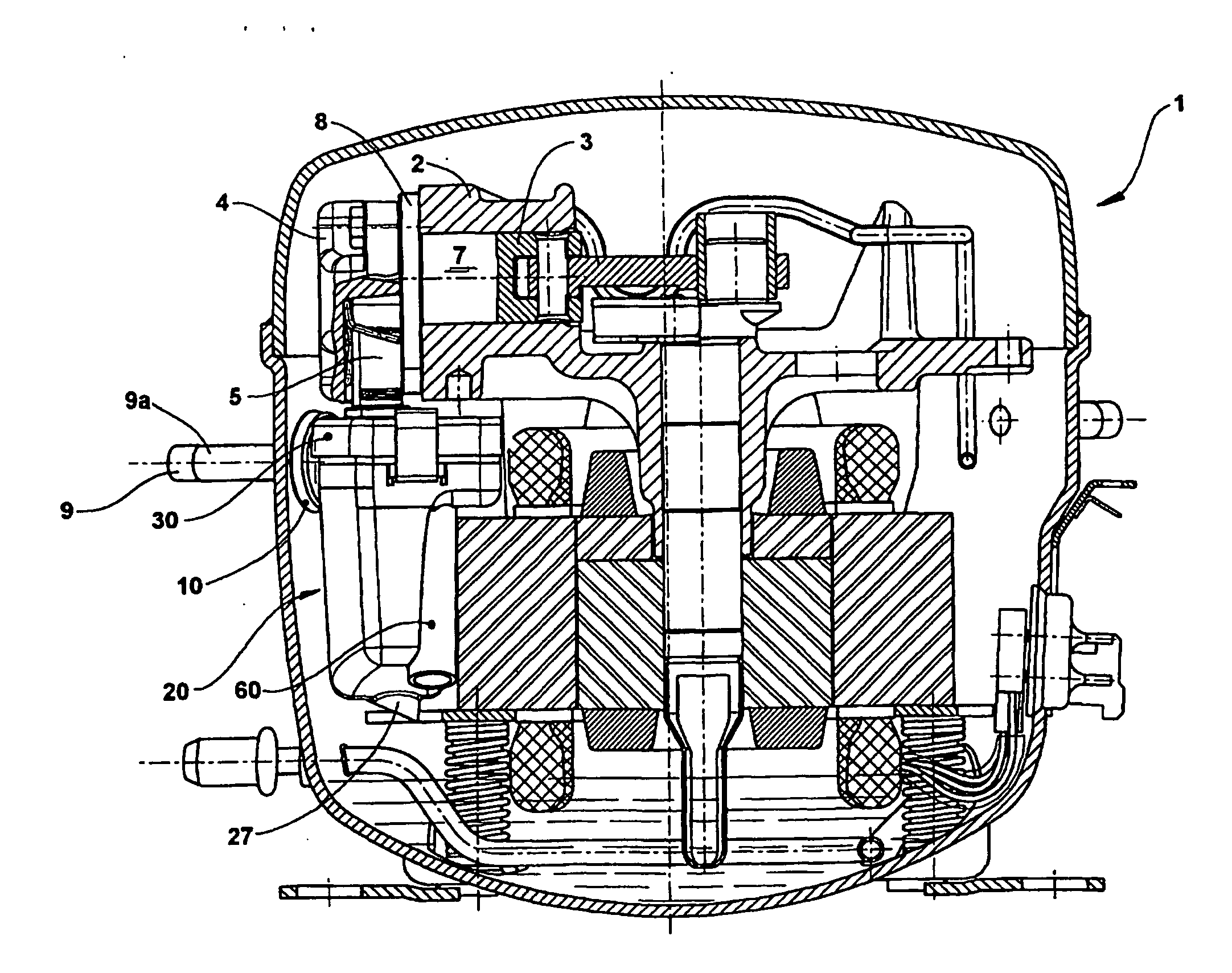
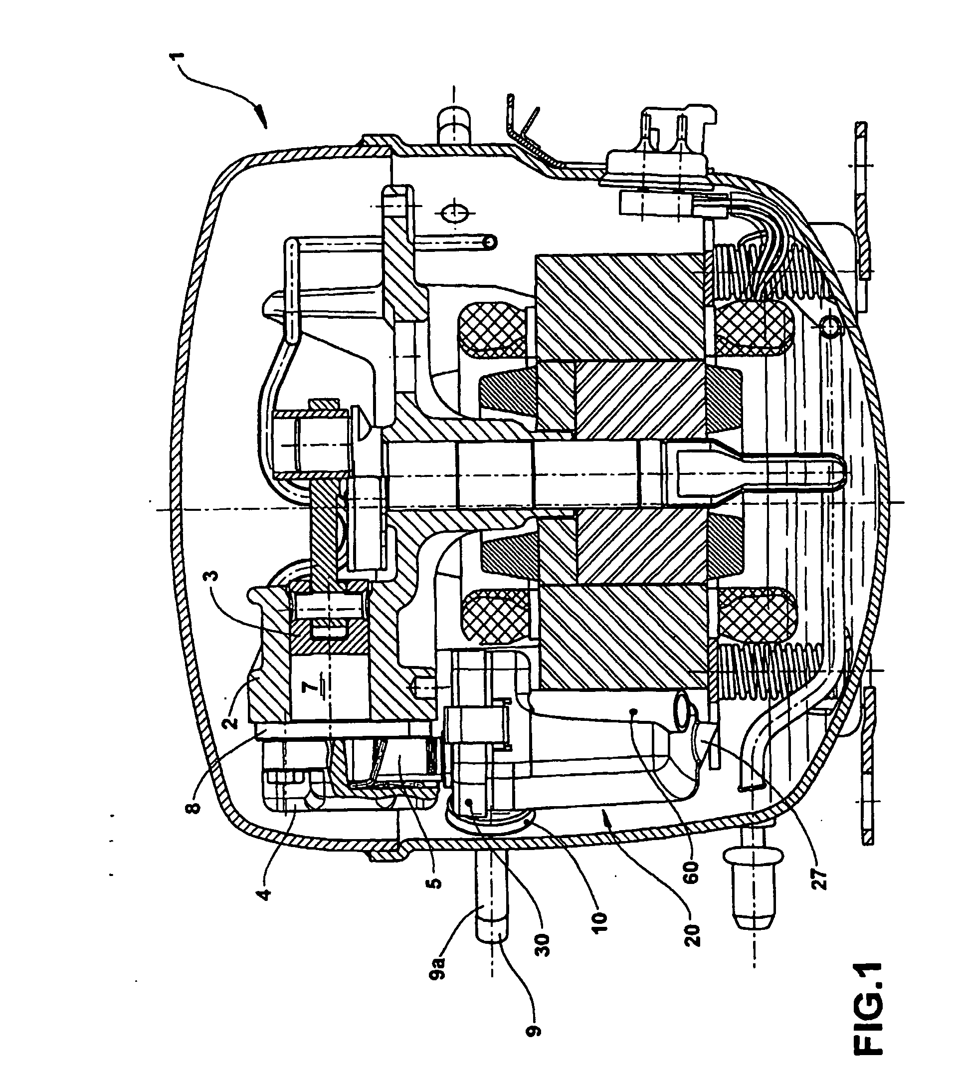
[0020] The present invention will be described for a compressor of the type used in refrigeration systems and comprising: inside a hermetic shell 1, a motor-compressor assembly having a cylinder block where is defined a cylinder 2 lodging, at one end, a reciprocating piston 3, and having an opposite end closed by a cylinder cover 4 defining therewithin a housing 5 for adaptation of the suction muffler, and a discharge chamber 6 (FIG. 3) in selective fluid communication with a compression chamber 7 defined inside the cylinder 2 between a top portion of the piston 3 and a valve plate 8 provided between the opposite end of the cylinder 2 and the cylinder cover 4, through suction orifices 8a and discharge orifices (not illustrated), which are provided on said valve plate 8 and selectively respectively closed by suction valves 8a and discharge valves (not illustrated).

[0021] According to the illustrations, the gas drawn by the compressor and coming from a suction line 9 of the refrigera...


PUM


Abstract

A suction muffler for a reciprocating hermetic compressor mounted inside a hermetic shell (1), said suction muffler comprising a hollow body (20) defining at least one acoustic chamber and provided with a gas inlet (22) connected to a suction line (9) by means of a tubular connector, and with a gas outlet (32) connected to a suction valve (8b) of the compressor, said equalizing chamber (60) being provided, on one side, with an opening (60a) to the interior of the hermetic shell (1) and, on the other side, with a fluid communication (61) with the acoustic chamber, said equalizing chamber (60) being dimensioned to minimize, simultaneously, the noises of the gas pulses inside the suction muffler, the mixture of said gas with that contained inside the hermetic shell (1), and the pressure differential between the interior of the latter and the suction line (9), upon operation of the compressor after a stop period.

Description

FIELD OF THE INVENTION [0001] The present invention refers to a suction muffler to be mounted at the refrigerant gas supply region in a reciprocating hermetic compressor, particularly in a reciprocating hermetic compressor of direct suction used in small refrigeration systems. BACKGROUND OF THE INVENTION [0002] Reciprocating hermetic compressors have their suction provided with an acoustic dampening system (acoustic filters or suction mufflers) provided inside the shell and which conducts the gas coming from the suction line to the suction valve. [0003] This component executes several functions that are important to the adequate operation of the compressor, such as gas conduction, acoustic dampening and, in some cases, thermal insulation of the gas that is drawn to the inside of the cylinder. [0004] The suction muffler generally consists of a sequence of volumes and tubes that conduct the gas coming from the suction line directly to the suction valve. This gas displacement produces ...

Claims


Application Information

Patent Timeline
IPC IPC(8): F04B39/00
CPCY10S181/403F04B39/0061F04B39/00F04B35/04
Inventor LILIE, DIETMAR ERICH BERNHARDPOSSAMAI, FABRICIO CALDEIRA
Owner EMBRACO IND DE COMPRESSORES E SOLUCOES EM REFRIGERACAO LTDA
Learn More