
mems part and method for manufacturing

A technology of components and structures, applied in the direction of microstructure devices composed of deformable elements, electrical components, piezoelectric devices/electrostrictive devices, etc., can solve problems such as sensor performance degradation

Active Publication Date: 2016-06-08
TDK CORPARATION
View PDF4 Cites 0 Cited by
  • Summary
  • Abstract
  • Description
  • Claims
  • Application Information

AI Technical Summary

Problems solved by technology

But at the same time, the performance of the sensor will be significantly reduced

Method used


Image

  • mems part and method for manufacturing
  • mems part and method for manufacturing
  • mems part and method for manufacturing

Examples


Embodiment Construction

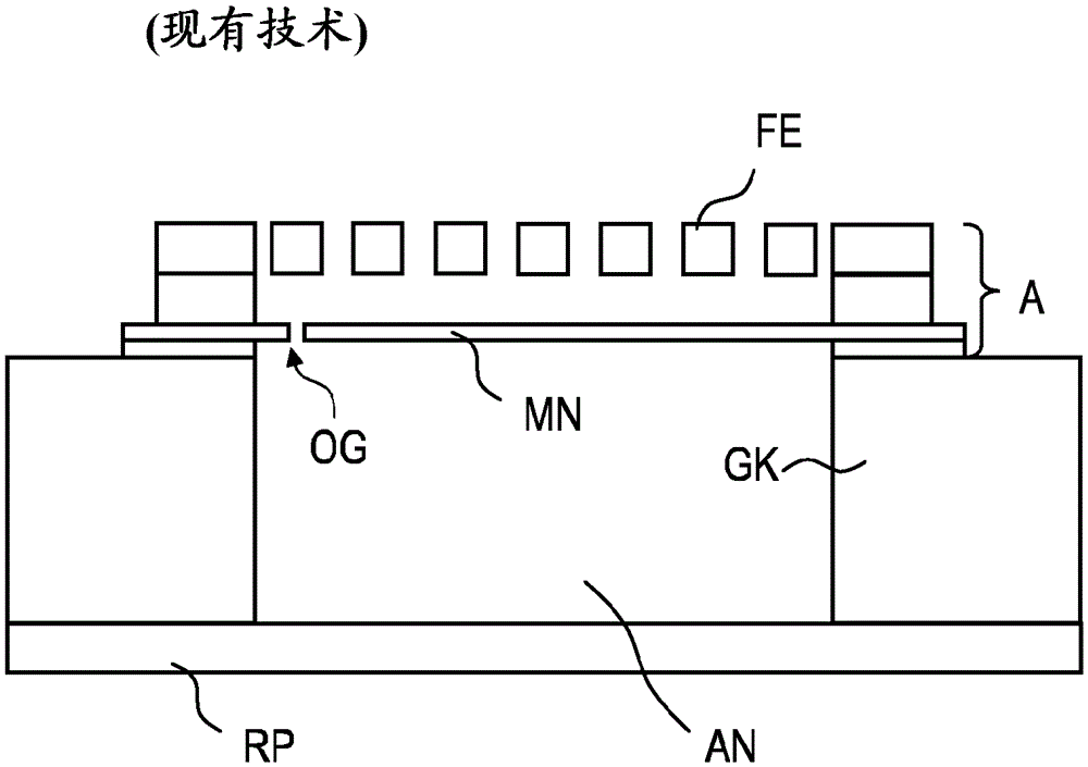
[0033] Figure 1A A MEMS microphone known from the prior art is shown in schematic section. The basic operating principle of the components is explained below on the basis of this figure. Apart from the opening and the function, the design and function of the component according to the invention are compatible with the known MEMS components described here.

[0034] The MEMS component has a crystalline base body GK, in which recesses AN are preferably structured with vertical side walls. Arranged on the upper side of the base body GK is a structure A comprising a plurality of functional layers. This construction comprises a first functional layer MN designed as a membrane, and a second functional layer designed as a fixed electrode FE. The two functional layers of configuration A cover the recess and are arranged at a distance from each other and parallel. The first functional layer MN spans the entire recess and seals it upwards. The remaining volume sealed in this way is th...


PUM


Abstract

A MEMS component is proposed with a crystalline matrix (GK), a recess (AN) and a structured construction (A) surrounding this recess, wherein in a first functional layer (MN) an opening (OG), an opening The effective opening cross-section of MN varies according to the pressure difference on both sides of the first functional layer (MN).

Description

Background technique [0001] For measuring pressure and especially as a microphone, MEMS devices designed as sensors can be used. These MEMS sensors can operate according to the capacitor principle and then have an electrically conductive diaphragm and fixed electrodes arranged at a distance. The capacitance change due to the deflection of the diaphragm can be detected as a measured value. [0002] The sensitivity of a MEMS microphone is additionally determined by the mechanical stability of its diaphragm. In order to be able to detect even small pressure differences, efforts have been made to use thin and light deflectable diaphragms. However, this has the disadvantage that the diaphragms can be damaged under the influence of high sound pressure or rapid pressure increases. In addition, the diaphragm and / or the fixed electrode can be broken off and thus the microphone or pressure sensor can be destroyed. [0003] The possibility that the sensitivity to rapidly increasing h...

Claims


Application Information

Patent Timeline
Patent Type & Authority Patents(China)
IPC IPC(8): B81B3/00
CPCB81B3/0072H02N1/08
Inventor P.H.O.罗姆巴赫
Owner TDK CORPARATION
Learn More