Methods for electrochemically fabricating structures using adhered masks, incorporating dielectric sheets, and/or seed layers that are partially removed via planarization

a technology of electrochemical fabrication and masking material, applied in the field of three-dimensional structure formation, can solve the problem of destructive separation of masking material from the substra

Inactive Publication Date: 2005-02-10
MICROFAB
View PDF8 Cites 58 Cited by
  • Summary
  • Abstract
  • Description
  • Claims
  • Application Information

AI Technical Summary

Problems solved by technology

The CC mask plating process is distinct from a “through-mask” plating process in that in a through-mask plating process the separation of the masking material from the substrate would occur destructively.

Method used


Image

  • Methods for electrochemically fabricating structures using adhered masks, incorporating dielectric sheets, and/or seed layers that are partially removed via planarization
  • Methods for electrochemically fabricating structures using adhered masks, incorporating dielectric sheets, and/or seed layers that are partially removed via planarization
  • Methods for electrochemically fabricating structures using adhered masks, incorporating dielectric sheets, and/or seed layers that are partially removed via planarization

Examples


first embodiment

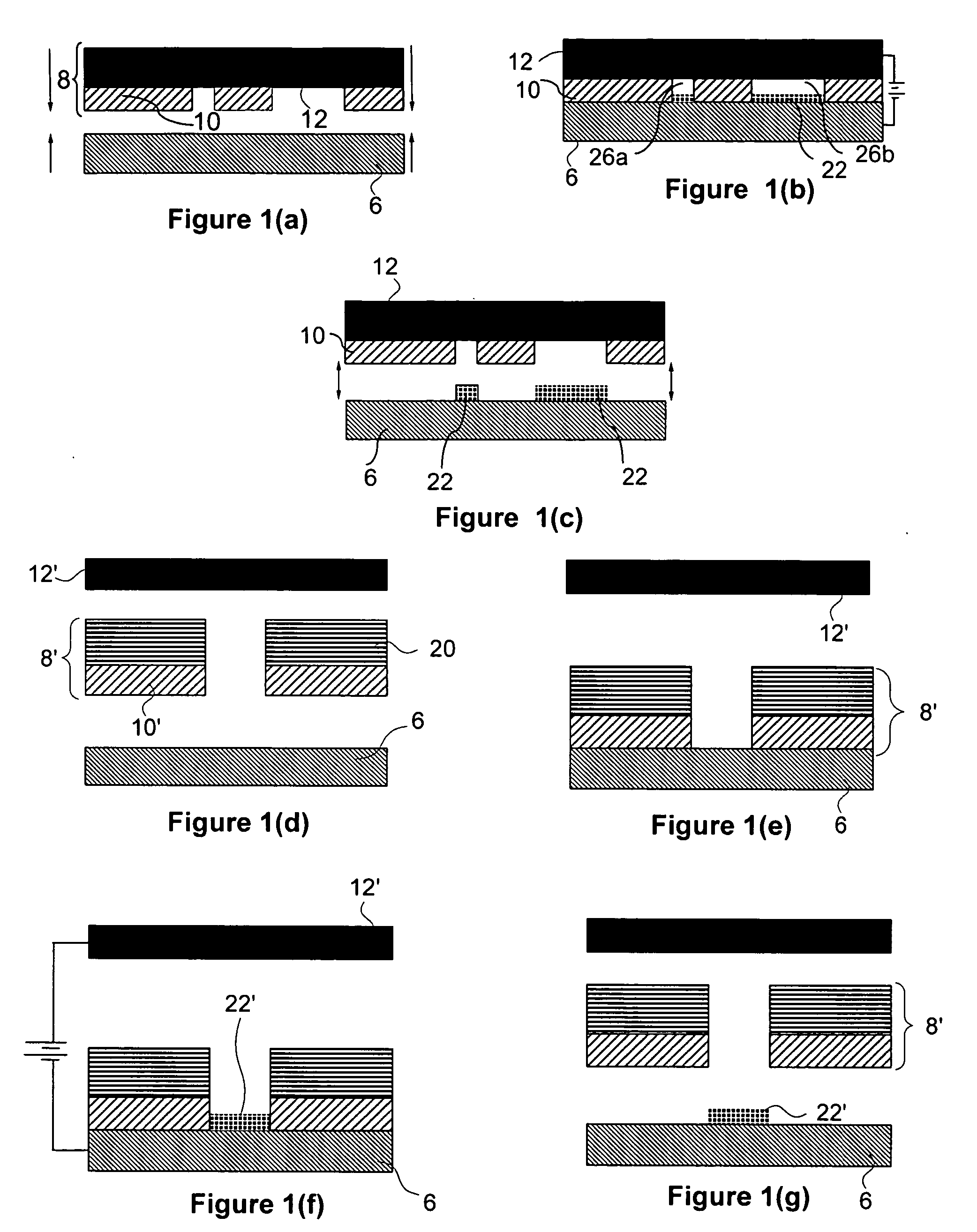
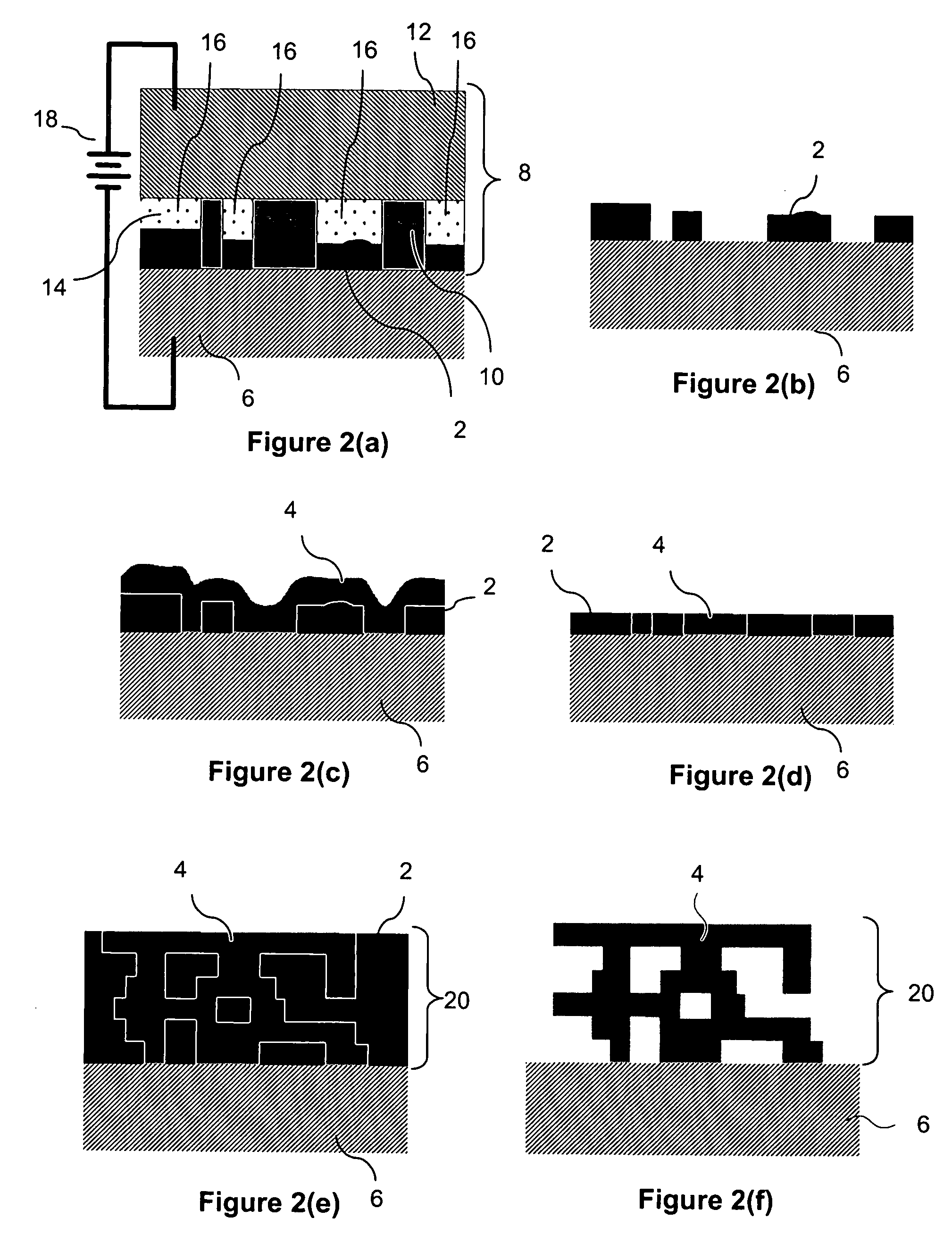
[0091]FIG. 5 provides a generalized process flowchart of the invention which forms a three-dimensional structure from a conductive material and from a dielectric material. The process of FIG. 5 begins with block 102 and then moves forward to block 104. Block 104 calls for the defining of a variable “n” to be that of the number of the current layer. It also calls for the defining of a number “N” which corresponds to a number of the final layer of the structure to be formed. After the defining of variables and parameters, the process moves forward to block 106 which calls for setting of variable “n” to a value of 1. The process then moves forward to block 108 which calls for the supplying of a substrate which may include one or more previously formed layers of material or deposits of material.

[0092] Next the process moves forward to block 112 which calls for the applying of a dielectric material onto the substrate (or previously formed layer during a second or subsequent loop through ...

second embodiment

[0116]FIG. 8 provides a generalized process flowchart of the invention which modifies a substrate by applying a conductive material and a dielectric material thereto.

[0117] The embodiment of FIG. 8 is similar to that of FIG. 5 with the exception that it calls for the formation of a single layer of material on a substrate. Operations 402, 408, 412, 414, 416, 418 and 426 correspond essentially and respectively to operations 102, 108, 112, 114, 116, 118 and 126 of FIG. 5.

third embodiment

[0118]FIG. 9 provides a generalized process flowchart of the invention which forms a three-dimensional structure from a conductive material and from a dielectric material. The embodiment of FIG. 9 is similar to that of FIG. 5 with the exception that it contemplates the possibility that some other generalized process may be used to form one or more of the layers of the structure. In FIG. 9 similar operations to those shown in FIG. 5 are indicated with equivalent reference numbers. The process of FIG. 9 and that of FIG. 5 proceed in similar manners up through operation 108 after which the process of FIG. 9 moves forward to decision block 130 where an inquiry is made as to whether or not layer “n” is to be formed using a single dielectric and a single conductive material.

[0119] If this inquiry produces a positive response the process proceeds along a path that implements elements 112-124 in a manner analogous to that of the embodiment of FIG. 5. If decision block 130 produces a negativ...


PUM

PropertyMeasurementUnit
dielectric constantaaaaaaaaaa
temperatureaaaaaaaaaa

Abstract

Embodiments of the present invention provide mesoscale or microscale three-dimensional structures (e.g. components, device, and the like). Embodiments relate to one or more of (1) the formation of such structures which incorporate sheets of dielectric material and / or wherein seed layer material used to allow electrodeposition over dielectric material is removed via planarization operations; (2) the formation of such structures wherein masks used for at least some selective patterning operations are obtained through transfer plating of masking material to a surface of a substrate or previously formed layer, and / or (3) the formation of such structures wherein masks used for forming at least portions of some layers are patterned on the build surface directly from data representing the mask configuration, e.g. in some embodiments mask patterning is achieved by selectively dispensing material via a computer controlled inkjet nozzle or array or via a computer controlled extrusion device.

Description

RELATED APPLICATIONS [0001] This application claims benefit of the following U.S. Provisional Patent Applications 60 / 468,979, filed May 7, 2003; 60 / 469,053, filed May 7, 2003; and 60 / 533,891, filed Dec. 31, 2003. Each of these applications is hereby incorporated herein by references as if set forth in full herein.FIELD OF THE INVENTION [0002] The present invention relates generally to the field of electrochemical fabrication and the associated formation of three-dimensional structures (e.g. microscale or mesoscale structures). In particular, it relates to one or more of (1) the formation of such structures which incorporate sheets of dielectric material and / or wherein seed layer material used to allow electrodeposition over dielectric material is removed via planarization operations; (2) the formation of such structures wherein masks used for at least some selective patterning operations are obtained through transfer plating of masking material or precursor material to a surface of ...

Claims


Application Information

Patent Timeline
Patent Type & Authority Applications(United States)
IPC IPC(8): B05D1/32C23C18/16C25D5/02C25D5/10H01L21/768
CPCC25D5/022C25D5/10H01L21/7682C23C18/1657C25D1/003C23C18/1605H01L21/76838B33Y10/00
Inventor LOCKARD, MICHAEL S.SMALLEY, DENNIS R.LARSEN, WILLA M.CHEN, RICHARD T.
Owner MICROFAB
Why Eureka
Try Eureka