
Semiconductor device including interlayer interconnecting structures and methods of forming the same

Inactive Publication Date: 2009-01-29
SAMSUNG ELECTRONICS CO LTD
View PDF9 Cites 162 Cited by
  • Summary
  • Abstract
  • Description
  • Claims
  • Application Information

AI Technical Summary

Benefits of technology

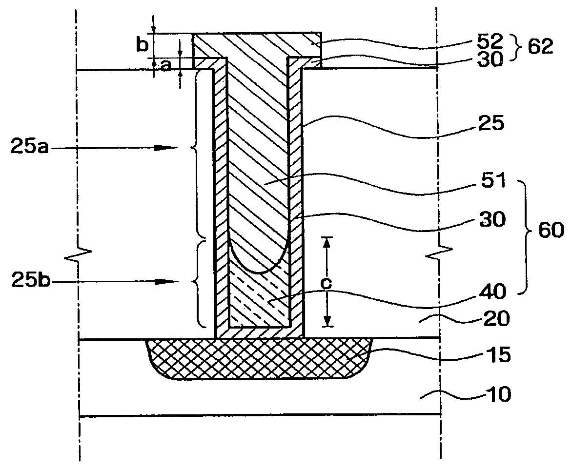
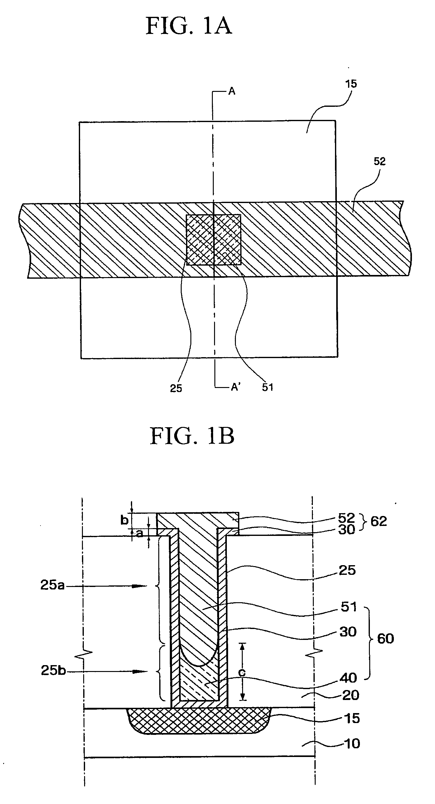
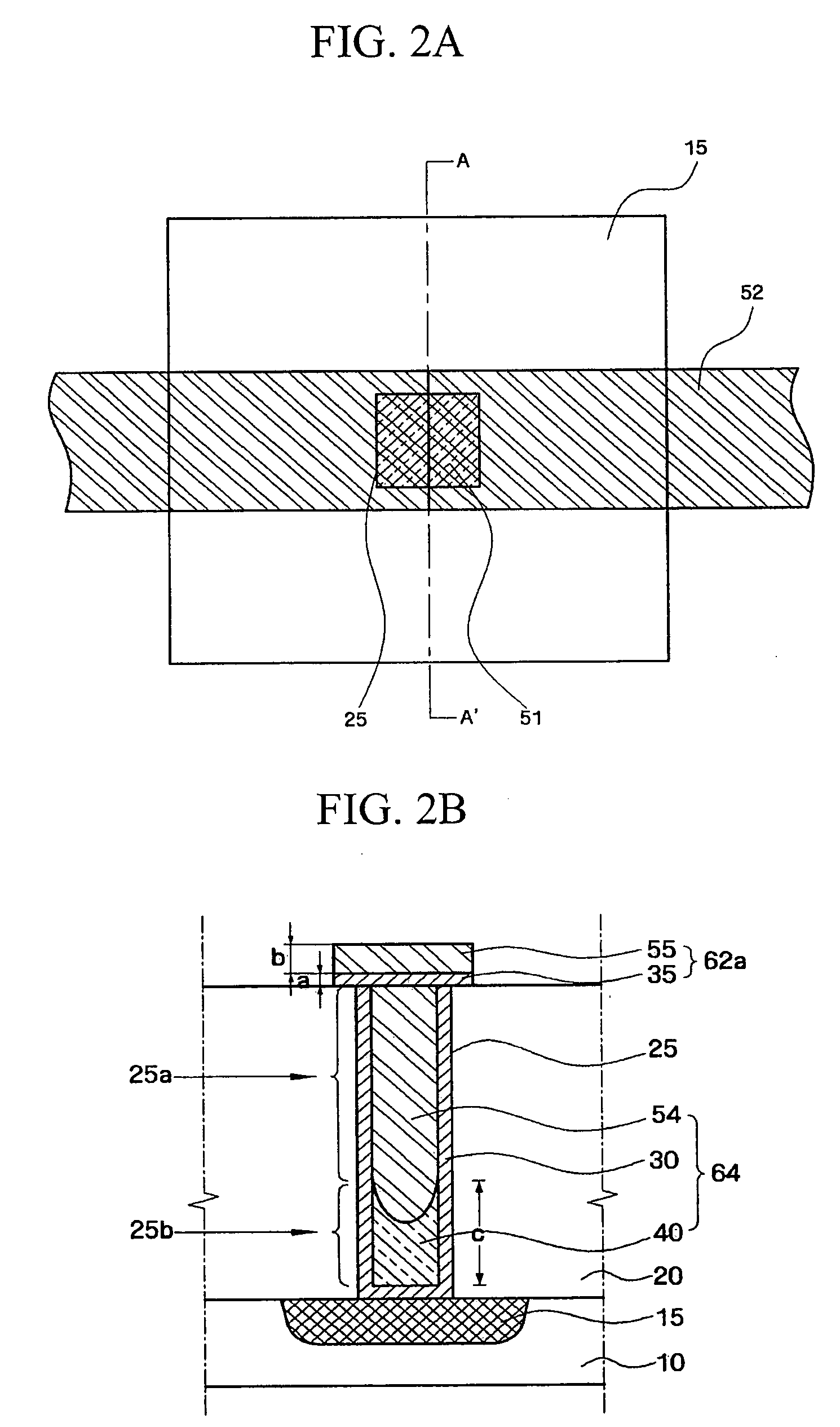
[0006]Embodiments of the present invention are directed to semiconductor devices and methods of forming the same wherein interlayer connecting structures provide low-resistivity connectivity with reduced capacitance in the resulting device. In particular, the embodiments of the present invention provide interlayer connecting structures that have a reduced pattern thickness on the interlayer dielectric layer for reducing the interface area of neighboring interconnect patterns. This is achieved while providing a lowered bulk metal resistance, as a seed layer comprising cobalt is used. At the same time, the presence of a relatively thick barrier layer in a lower portion of the interlayer connecting structure prevents chemical attack of the underlying silicide contact region during subsequent metal fill fabrication procedures. In addition, the presence of the barrier layer prevents diffusion of metal during the subsequent metal fill procedures into the underlying substrate or contact region, which diffusion can otherwise operate to increase contact resistance at the interface of the interlayer connecting structure and contact region.
[0021]The barrier layer can protect the underlying contact region when the metal layer is provided in the opening.

Problems solved by technology

However, as the patterns used to form device components become smaller and as the space between adjacent patterns is decreased, there is a greater likelihood of signal interference for signals propagating over neighboring interconnect patterns and components.
With further integration of devices, certain materials that are conventionally used for forming conductive interconnect patterns can become relatively unstable due to characteristics of the material that manifest themselves as the patterns become smaller.

Method used


Image

  • Semiconductor device including interlayer interconnecting structures and methods of forming the same
  • Semiconductor device including interlayer interconnecting structures and methods of forming the same
  • Semiconductor device including interlayer interconnecting structures and methods of forming the same

Examples


Embodiment Construction

[0047]Embodiments of the present invention will now be described more fully hereinafter with reference to the accompanying drawings, in which preferred embodiments of the invention are shown. This invention may, however, be embodied in different forms and should not be construed as limited to the embodiments set forth herein. Like numbers refer to like elements throughout the specification.

[0048]It will be understood that, although the terms first, second, etc. are used herein to describe various elements, these elements should not be limited by these terms. These terms are used to distinguish one element from another. For example, a first element could be termed a second element, and, similarly, a second element could be termed a first element, without departing from the scope of the present invention. As used herein, the term “and / or” includes any and all combinations of one or more of the associated listed items.

[0049]It will be understood that when an element is referred to as b...


PUM


Abstract

In a method of forming a semiconductor device, and a semiconductor device formed according to the method, an insulating layer is provided on an underlying contact region of the semiconductor device. An opening is formed in the insulating layer to expose the underlying contact region. A seed layer is provided on sidewalls and a bottom of the opening, the seed layer comprising cobalt. A barrier layer of conductive material is provided in a lower portion of the opening, the seed layer being exposed on sidewalls of an upper portion of the opening. A metal layer is provided on the barrier layer in the opening to form an interlayer contact, the metal layer contacting the seed layer at the sidewalls of the upper portion of the opening.

Description

RELATED APPLICATIONS[0001]This application claims priority under 35 U.S.C. 119 to Korean Patent Application No. 10-2007-0074800, filed on Jul. 25, 2007, and Korean Patent Application No. 10-2008-0021625, filed on Mar. 7, 2008, the content of which are incorporated herein by reference in its entirety.BACKGROUND OF THE INVENTION[0002]With the continued emphasis on highly integrated electronic devices, there is an ongoing need for semiconductor devices that operate at higher speed and lower power and have increased device density. To achieve these goals, it is necessary for devices to be formed with increased integration and for device components to be formed of lower-resistivity materials. However, as the patterns used to form device components become smaller and as the space between adjacent patterns is decreased, there is a greater likelihood of signal interference for signals propagating over neighboring interconnect patterns and components.[0003]Device performance is highly depend...

Claims


Application Information

Patent Timeline
IPC IPC(8): H01L21/768H01L23/48
CPCH01L21/76843H01L21/76846H01L21/76868H01L21/76871H01L23/485H01L27/105H01L27/10885H01L2924/0002H01L27/10888H01L27/11521H01L27/11526H01L27/24H01L2924/00H10B12/482H10B12/485H10B41/40H10B41/30H10B63/10H10B63/00
Inventor KIM, HYUN-SUKIM, DAEYONGLEE, EUN-OKKIM, BYUNGHEELEE, JANG-HEEJUNG, EUN-JICHOI, GILHEYUN
Owner SAMSUNG ELECTRONICS CO LTD
Learn More