Floating connector

a technology of floating connectors and connectors, which is applied in the direction of incorrect coupling prevention, coupling device connection, electrical apparatus, etc., can solve the problems of large connector size, affecting the effect of insulator housing protrusion, and complicated tasks, so as to reduce the possibility of separation, reliably absorb deviation, and strengthen the resistance to pull-out force in the height direction.

Active Publication Date: 2005-02-10
JST MFG CO LTD
View PDF5 Cites 21 Cited by
  • Summary
  • Abstract
  • Description
  • Claims
  • Application Information

AI Technical Summary

Benefits of technology

[0010] Moreover, as the floating parts of the contacts are of a plate form, the floating parts will flex easily when they are made to flex in their thickness direction, and the floating parts will tend to absorb the deviation in the position of the connector in relation to that of the counterpart connector. However, when the floating parts are made to flex in their width direction, the resistance will be greater, and it will be hard to absorb the deviation. Furthermore, as the intermediate parts of the contacts are merely put in the receiving parts of the guide insulator, there is a possibility that when the floating parts are flexed, the contacting parts will shift in relation to the guide insulator. This, in turn, leads to a possibility that defective contacts will arise between the contacting parts of the contacts and the counterpart contacts or a possibility that the contacting parts of the contacts will contact the counterpart contacts and buckle themselves.
[0011] The present invention was made in view of these points, and its object is to provide a floating connector wherein a base housing and a slide housing are related to each other by means of protruding parts protruding in the width direction and grooves into which the protruding parts are inserted, both the base housing and the slide housing are elastically coupled together by means of contacts, which penetrate both the base housing and the slide housing and both ends thereof are pressed into the respective housings, so that strengths against pull-out forces in the height direction are high and both housings are resistant to separation, the slide housing slides in any direction perpendicular to the height direction to reliably absorb the deviation in the position of the floating connector in relation to that of the counterpart connector without resulting in any defective contact with the counterpart contacts nor buckling of the contacts, and moreover, the floating connector can be produced easily, and the floating connector has a high self-supportability through setting an appropriate rigidity of the contacts.
[0014] In the case of this floating connector, the slide housing is enabled to slide in relation to the base housing in any direction perpendicular to the height direction and is restrained from shifting in the height direction by inserting the protruding parts into the grooves, leaving spaces in both the width direction and the depth direction. Moreover, if the slide housing slides in relation to the base housing, the floating parts of the contacts will undergo elastic deformation to absorb it. Accordingly, even when there is a deviation in the position of the floating connector in relation to the counterpart connector, this deviation will be absorbed by the sliding of the slide housing and the floating connector will be engaged with the counterpart connector. In that case, the strength against the pull-out force in the height direction will increase, reducing the possibility of separation of the base housing and the slide housing. Moreover, the slide housing is able to slide freely in any direction perpendicular to the height direction to reliably absorb the deviation in the position of the floating connector in relation to the counterpart connector. As the contacting part of the contact is pressed into the second through hole of the slide housing, even when the floating part is flexed, the contacting part will not shift in relation to the slide housing, the contacting part of the contact will not have defective contact between it and the counterpart contact, and the contacting part of the contact will not contact the counterpart connector to buckle itself. The floating connector can be produced easily by inserting one of the base housing and the slide housing into the other, inserting the contacts into the first through holes and the second through holes and pressing the contacts into the base housing and the slide housing. Moreover, the floating connector with high self-supportability can be produced by properly setting the rigidity of the contacts.
[0015] In the floating connector of the present invention the base housing and the slide housing are related to each other by means of protruding parts protruding in the width direction and grooves into which the protruding parts are inserted, and both the base housing and the slide housing are elastically coupled together by means of contacts, which penetrate both the base housing and the slide housing and both ends thereof are pressed into the respective housings, hence the present invention successfully provided a floating connector wherein strengths against pull-out forces in the height direction are high and both housings are resistant to separation, the slide housing slides in any direction perpendicular to the height direction to reliably absorb the deviation in the position of the floating connector in relation to that of the counterpart connector without resulting in any defective contact with the counterpart contacts nor buckling of the contacts, and moreover, the floating connector can be produced easily, and the floating connector has a high self-supportability through setting an appropriate rigidity of the contacts.
[0017] With this arrangement, as an elastic flexure of the first plate face and an elastic flexure of the second plate face are synthesized to enable the contacting part and the connecting part to shift in any direction perpendicular to the height direction, thus the floating part is realized with a simple structure.

Problems solved by technology

As the contact of the multi-pole connector of Japanese Utility Model Examined Publication Heisei 7-22865 has the U-shaped upper spring and the U-shaped lower spring of the same orientation, its dimension in the first direction will be large, posing a problem of larger connector size.
Moreover, the tongue of the drop-off preventing means is not free from slackness even when it fits on the insulator housing because of its structure, hence there exists a relative shift of the contact in relation to the insulator housing, and the amount of protrusion of the contact from the insulator housing varies.
In the production of this connector device it is necessary to execute a task to fitting the pair of the first fitting-on pieces of the base insulator on the positioning stepped parts of the guide insulator and a task to press the holding parts of the contacts into the first receiving parts of the base insulator and putting the intermediate parts of the contacts in the second receiving parts of the guide insulator, hence the tasks are complicated.
This will require another task to flex the first fitting-on pieces and align them and insert the contacts into the receiving parts, thus the workability will be deteriorated.

Method used


Image

  • Floating connector
  • Floating connector
  • Floating connector

Examples


Embodiment Construction

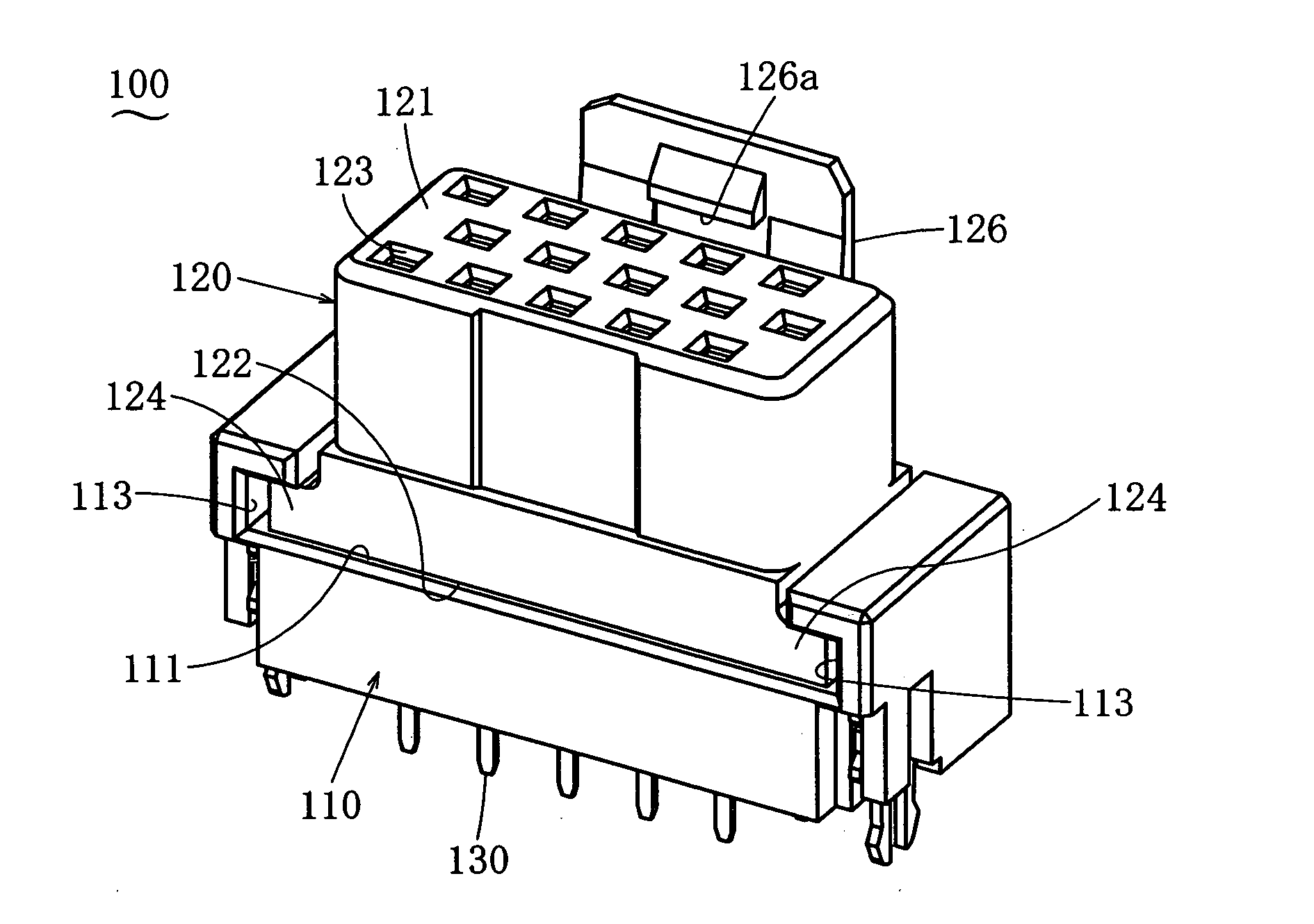
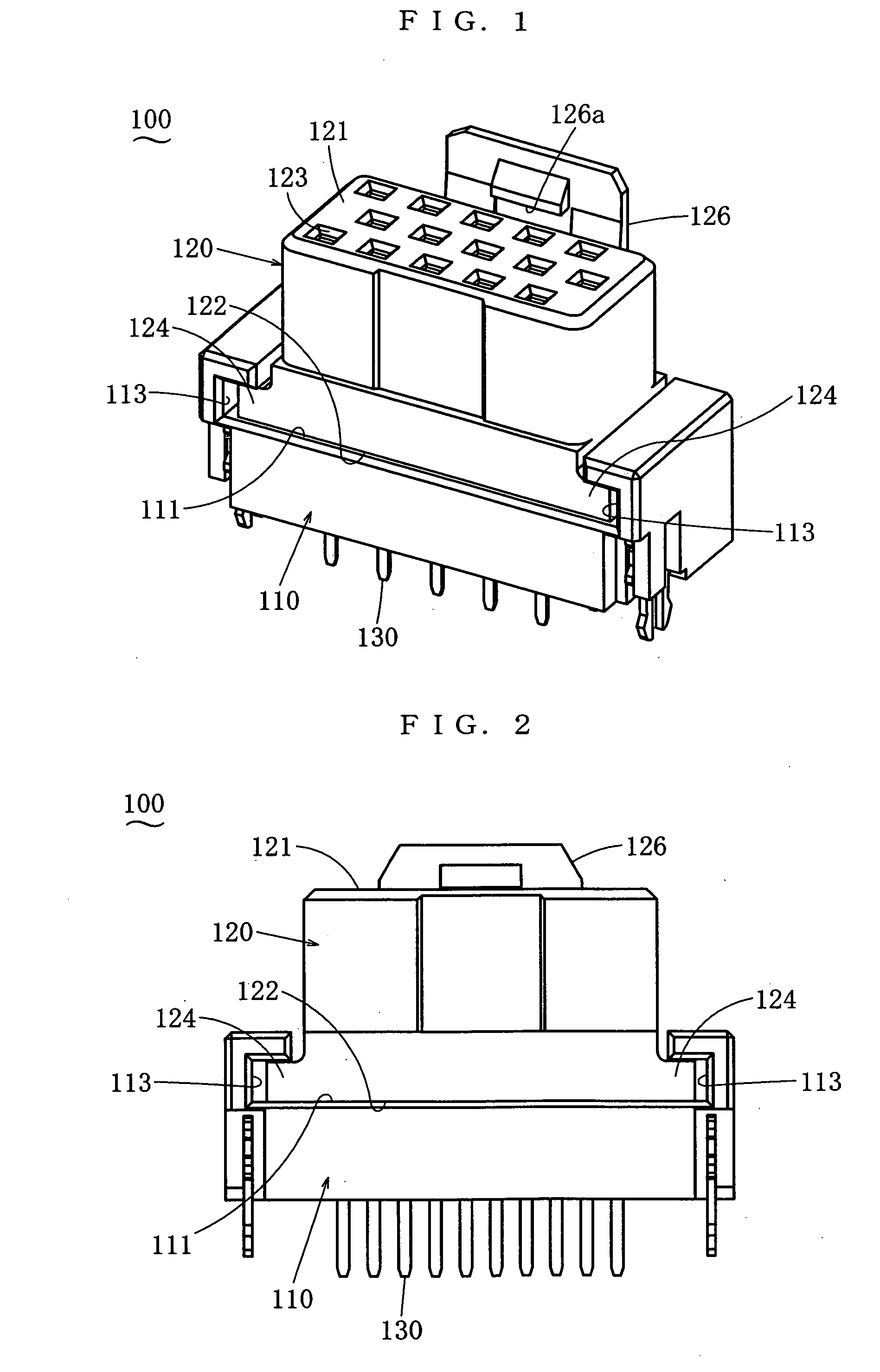
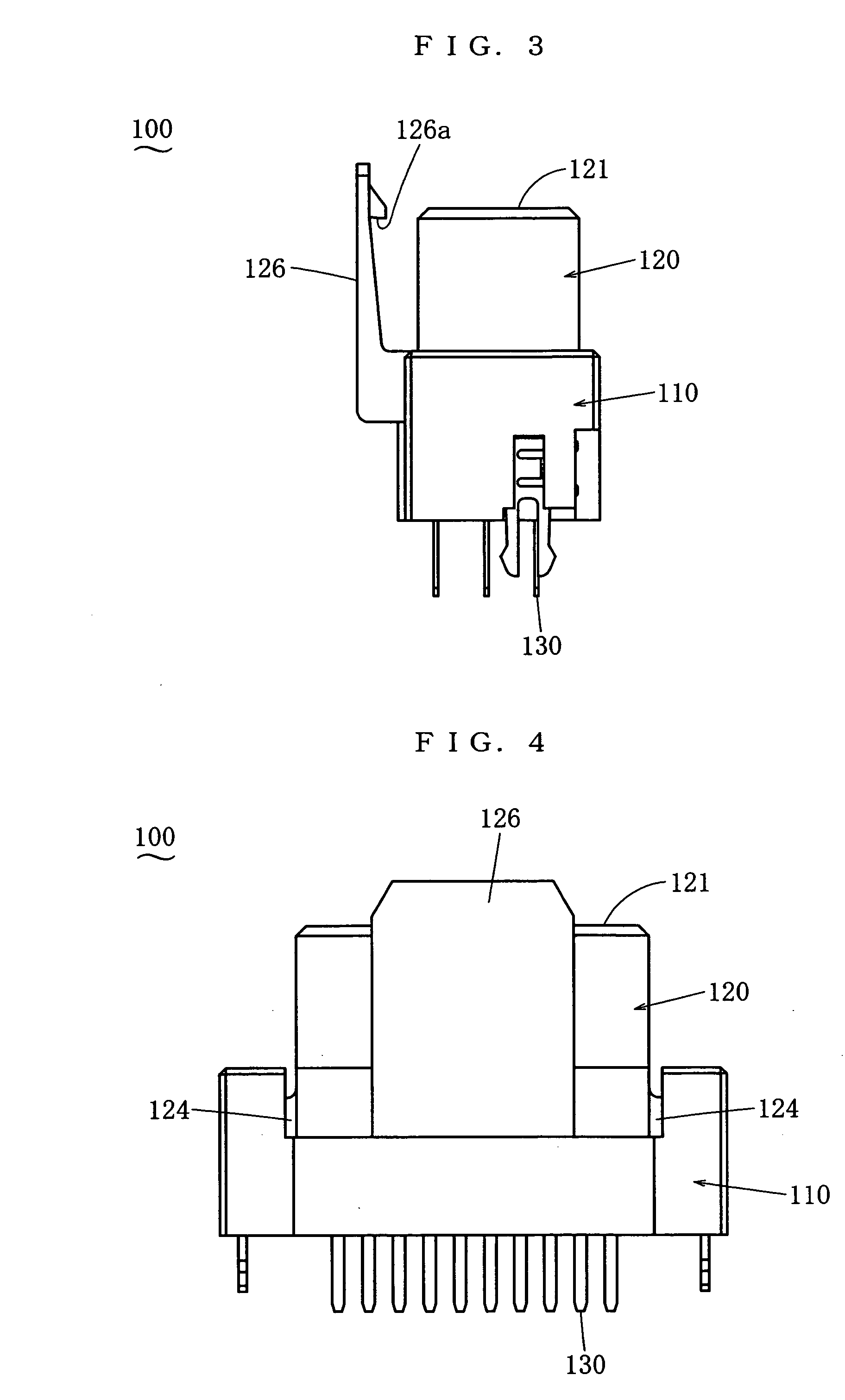
[0035] In the following, some embodiments of the present invention will be described. FIG. 1 through FIG. 7 show a floating connector 100 being an embodiment of the present invention. This floating connector 100 is engaged with or disconnected from a counterpart connector 200 shown in FIG. 11 and FIG. 12. Such engagement and disconnection are done in the height direction. The floating connector 100 of this embodiment is provided with a convex part 121, and the engagement is effected by inserting this convex part 121 into a concave part 211 of the counterpart connector 200. This relationship, however, may be reversed. The floating connector 100 of this embodiment is provided with female contacts 130, and the connection is effected when these contacts 130 are engaged with male contacts 220 of the counterpart connector 200. This relationship, however, may be reversed. A depth direction, a width direction and a height direction all being perpendicular to each other are assumed and the s...


PUM


Abstract

To provide a floating connector wherein strengths against pull-out forces in the height direction are high and both housings are resistant to separation, the slide housing slides in any direction perpendicular to the height direction to reliably absorb the deviation in the position of the floating connector in relation to that of the counterpart connector without resulting in any defective contact with the counterpart contacts nor buckling of the contacts, the floating connector can be produced easily, and the floating connector has a high self-supportability through setting an appropriate rigidity of the contacts. It is a floating connector wherein the connecting parts of the contacts are pressed into the base housing, the contacting parts of the contacts are pressed into the slide housing, and both housings are so related to each other by means of protruding parts protruding in the width direction and grooves into which the protruding parts are inserted that both housings can slide in any directions perpendicular to the height direction.

Description

BACKGROUND OF THE INVENTION [0001] 1. Field of the Invention [0002] The present invention belongs to the field of electric connectors and relates to a floating connector that can engage with a counterpart connector, even if there is a deviation in its position in relation to the counterpart connector, by absorbing that deviation. [0003] 2. Related Art [0004] Japanese Utility Model Examined Publication Heisei 7-22865 discloses a multi-pole connector wherein a plurality of contact fixing holes are provided inside an insulator housing for receiving and holding contacts, each of which has a contacting part at the top end and a solder tail at the bottom, and inside each of the contact fixing holes a single fixing means for a contact is provided, into which a base part of the contacting part of the corresponding contact is forced and fixed. In the case of this multi-pole connector, in order to absorb and adjust relative positional deviations in two directions perpendicular to each other b...

Claims


Application Information

Patent Timeline
Patent Type & Authority Applications(United States)
IPC IPC(8): H01R13/631
CPCH01R12/716H01R13/6315
Inventor SHIOTA, KOJITONAI, YUICHIMATSUMOTO, MITSUHIRO
Owner JST MFG CO LTD
Why Eureka
Try Eureka