Terminal position assurance with forward interlocking face keying

a technology of forward interlocking face and position assurance, which is applied in the direction of coupling contact members, coupling device connections, securing/insulating coupling contact members, etc., can solve the problems of difficult, if not impossible, to determine if the corresponding connectors are fully engaged, and the connector components are engaged

Inactive Publication Date: 2005-02-10
TE CONNECTIVITY CORP
View PDF32 Cites 6 Cited by
  • Summary
  • Abstract
  • Description
  • Claims
  • Application Information

AI Technical Summary

Benefits of technology

[0011] In view of the foregoing and other problems, disadvantages, and drawbacks of the conventional terminal position assurance mechanisms, various embodiments of the present invention are disclosed herein. It is an advantage of various embodiments of the present invention to provide a terminal position assurance mechanism operable in an electrical connector assembly. It is another advantage of embodiments of the present invention to provide a fixed terminal position assurance mechanism used in electrical connector assemblies, thereby providing increased strength for the assembly. Still another advantage of embodiments of the present invention is to provide a terminal position assurance mechanism used in electrical connector assemblies which prevents damage to internal assembly components during vibration. Yet another advantage of embodiments of the present invention is to provide a terminal position assurance mechanism used in electrical connector assemblies which decreases the tooling involved in producing the electrical connector assembly.
[0016] Embodiments of the present invention overcome the several disadvantages of the conventional designs, and in particular, has an advantage over conventional terminal position assurance mechanisms.

Problems solved by technology

Conventional connector assemblies, as used in automobiles and other vehicles, often face several types of problems.
For example, one problem involves the engagement of the connector components.
Because the electrical connector assembly is mated and then sealed, it is often difficult, if not impossible, to determine if the corresponding connectors are fully engaged with one another prior to catastrophic fatigue and failure.
This is of particular concern when the assembly undergoes periods of vibration, which naturally occurs whenever the vehicle is in movement, or even if it is stationary and the engine is running.
Another problem involves unrestricted and excessive movement of the contact system within the electrical assembly housings, which invariably occurs during these periods of vibration.
However, such conventional systems do not provide for proper alignment of internal assembly components, and the conventional designs simply allow too much internal component movement to occur, thereby causing failure of the internal assembly components, and of the assembly housings themselves.
Still another problem with the conventional stabilization devices is that it is difficult to determine if the internal components, themselves, have been fully seated within the connector housings, especially after the housings have been sealed.
In fact, conventional stabilization mechanisms do not provide a proper manner with which to stabilize the plug housing component of the electrical connector assembly.
This causes failures during vibration because the plug housing is not fully captured by the cap housing.
Unfortunately, these conventional TPA devices do not provide adequate assurance that the internal terminals and other contact components are fully seated during periods of excessive vibration.
Nor do these conventional TPA devices prevent movement of the internal components of the assembly.
Another problem with the conventional stabilization mechanisms is that all molds of the electrical connector housing assemblies must be changed depending on the type of TPA members being used.
That is to say, the conventional designs are not robust.
As such, the conventional mechanisms do not provide sufficient stabilization for the mated pair assembly.
Although the conventional mechanisms use TPA members to align the two mated halves, such TPA members do not provide any benefits to combat against vibration and rocking issues.
Generally, because the TPA is a floating component within the assembly, it does not help stabilize the connector system interface.
Moreover, such stabilization mechanisms employing these designs are not robust, and require significant tooling.

Method used


Image

  • Terminal position assurance with forward interlocking face keying
  • Terminal position assurance with forward interlocking face keying
  • Terminal position assurance with forward interlocking face keying

Examples


Embodiment Construction

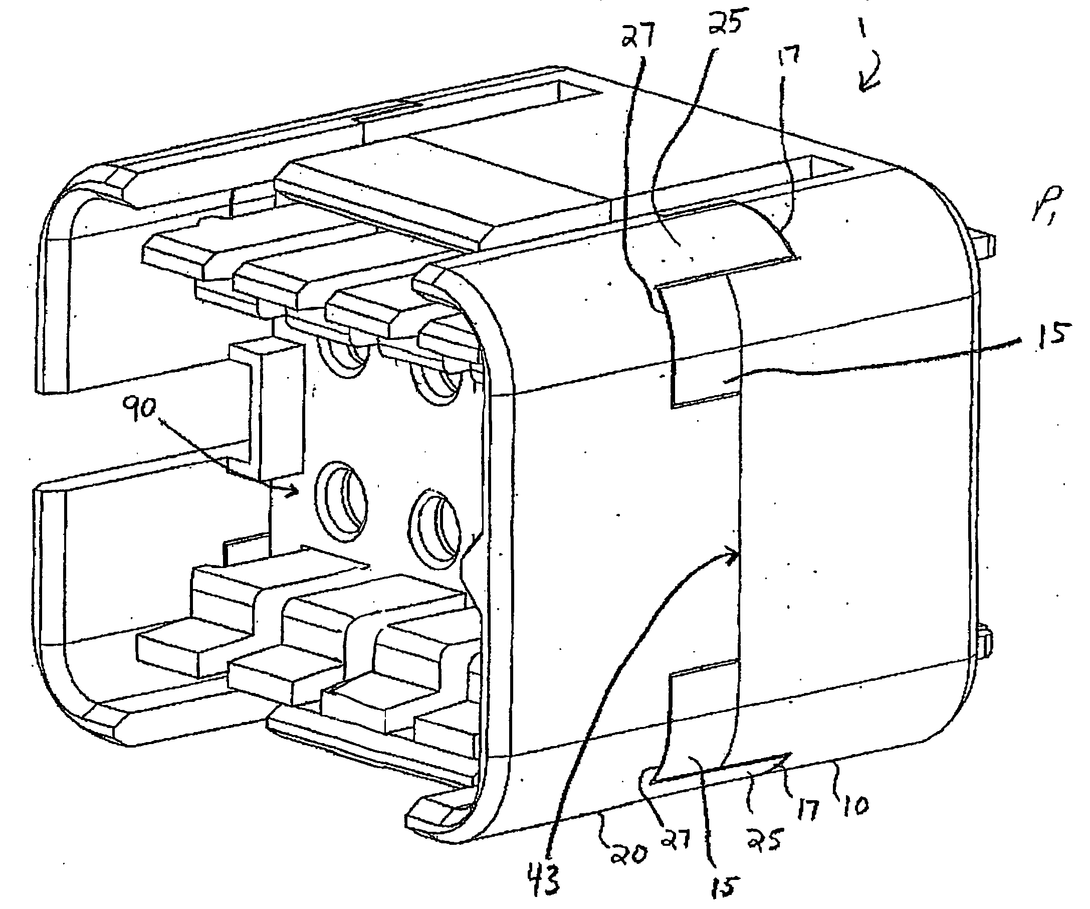
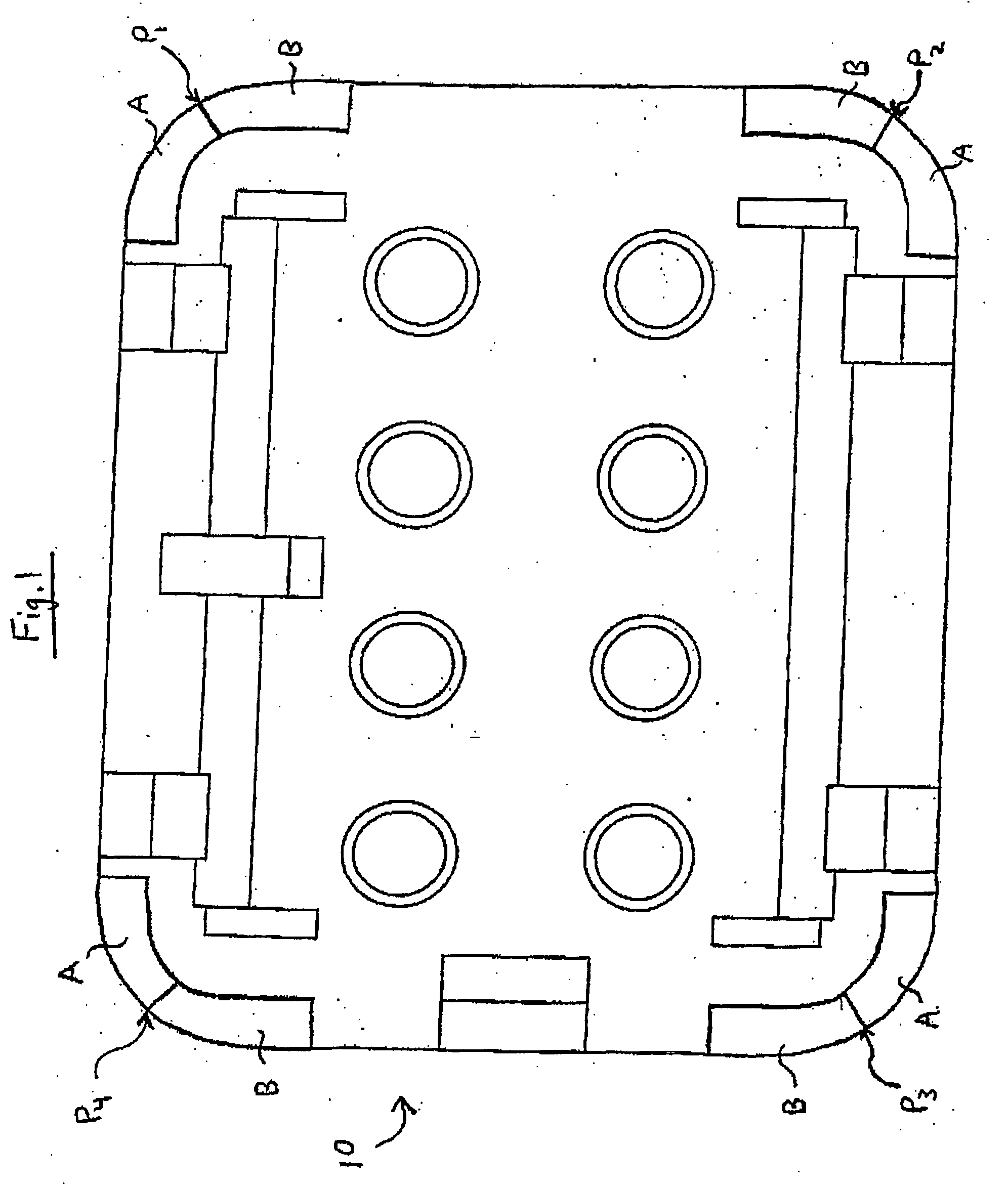
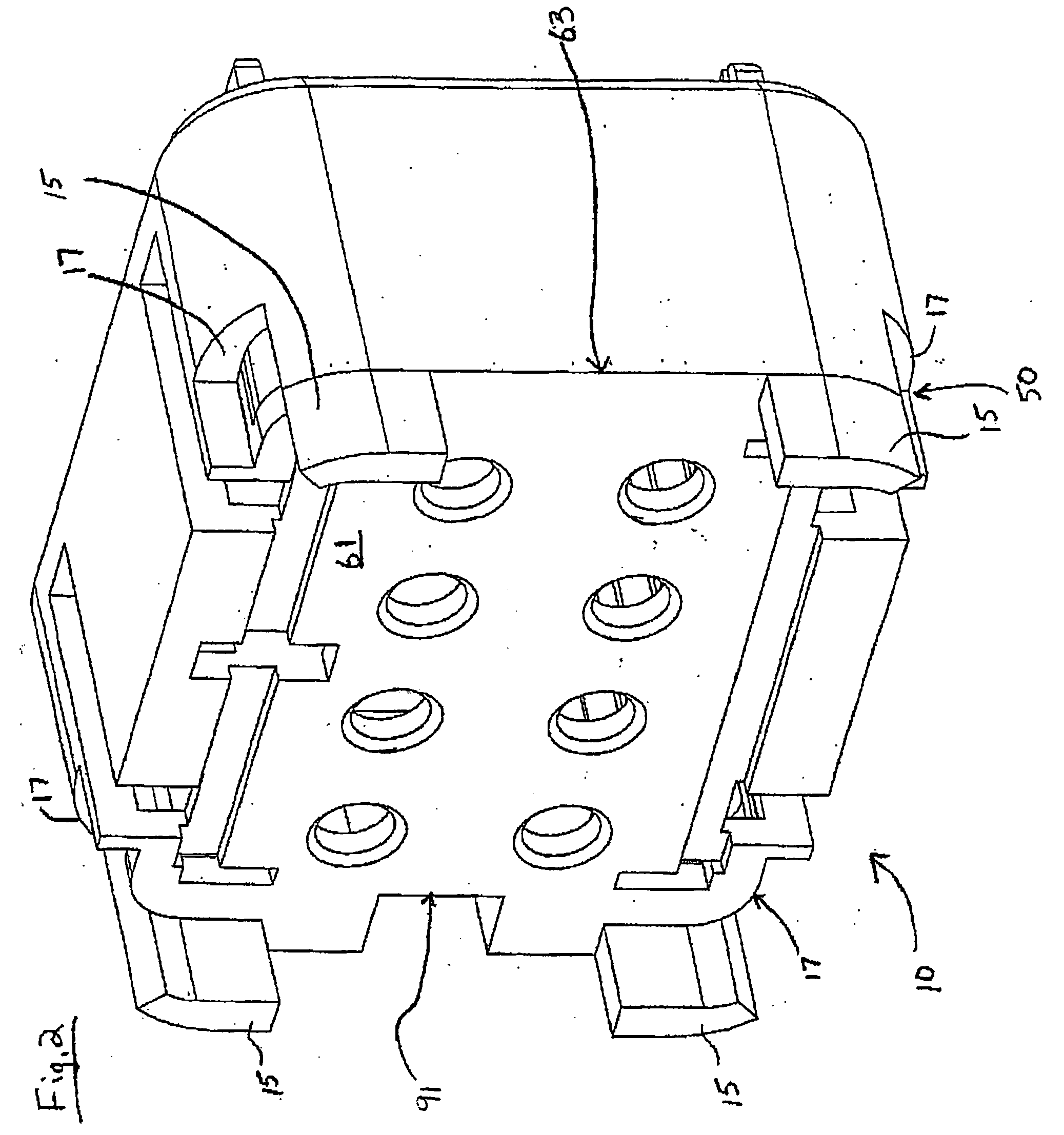
[0024] As previously mentioned, there is a need for a novel fixed terminal position assurance mechanism embodied with a forward interlocking face keying mechanism, which allows for multiple configurations (robust design), is a stronger design, and prevents damage to internal assembly components during periods of vibration of the assemblies, and which requires less tooling and parts involved to effectuate a proper electrical connector housing assembly. Embodiments of the present invention provide a fixed terminal position assurance mechanism operable in an electrical connector assembly, which provides increased assembly strength and allows for multiple configurations in the design of the assemblies, while simultaneously reducing the amount of tooling involved in the production of the housing assemblies. Additionally, the present invention provides terminal position assurance mechanisms that may also prevent improper mating of connectors.

[0025] Referring now to the drawings, and more...


PUM


Abstract

A connector assembly comprising a cap member having a plurality of fixed cap terminal position assurance mechanisms defined thereon, and a plug member having one or more of fixed plug terminal position assurance mechanisms defined thereon, wherein each of the cap terminal position assurance mechanisms fixably mate with each of the plug terminal position assurance mechanisms, wherein each of the cap and plug terminal position assurance mechanisms comprise a post projecting outwardly from each of the cap member and the plug member, and a cutout configured to fixably mate to the post. The cutout maybe configured adjacent the post, wherein the cap / plug terminal position assurance mechanisms are arranged proximate an outer rim of the cap / plug member or the cap / plug terminal assurance mechanism may be located generally in the center of the interface manifold.

Description

CROSS REFERENCE TO RELATED APPLICATIONS [0001] This application claims the benefit of U.S. Provisional Application Ser. No. 60 / 492,690 filed Aug. 5, 2003, which is hereby incorporated by reference in its entirety.FIELD OF THE INVENTION [0002] The present invention generally relates to terminal position assurance mechanisms, and more particularly to a terminal position assurance mechanism embodied with a forward interlocking face keying mechanism. BACKGROUND OF THE INVENTION [0003] Conventional connector assemblies, as used in automobiles and other vehicles, often face several types of problems. For example, one problem involves the engagement of the connector components. Because the electrical connector assembly is mated and then sealed, it is often difficult, if not impossible, to determine if the corresponding connectors are fully engaged with one another prior to catastrophic fatigue and failure. This is of particular concern when the assembly undergoes periods of vibration, whic...

Claims


Application Information

Patent Timeline
Patent Type & Authority Applications(United States)
IPC IPC(8): H01R13/436H01R13/645
CPCH01R13/4364H01R2201/26H01R13/6456
Inventor WARD, BOBBY GENEHOELSCHER, WOLFGANGGENIAC, JOSEPH EDWARD
Owner TE CONNECTIVITY CORP
Why Eureka
Try Eureka