Radio frequency power detecting circuit and method therefor

a technology of radio frequency power detection and detection circuit, which is applied in the direction of amplification control, electrical equipment, transmission, etc., can solve the problems of increasing the cost of battery power, and increasing the physical size of electronic devices and their associated batteries

a technology of radio frequency power detection and detection circuit, which is applied in the direction of amplification control, electrical equipment, transmission, etc., can solve the problems of increasing the cost of battery power, and increasing the physical size of electronic devices and their associated batteries

US20050032499A1Inactive Publication Date: 2005-02-10YUANTONIX

Image

  • Radio frequency power detecting circuit and method therefor
  • Radio frequency power detecting circuit and method therefor
  • Radio frequency power detecting circuit and method therefor

Examples


Embodiment Construction

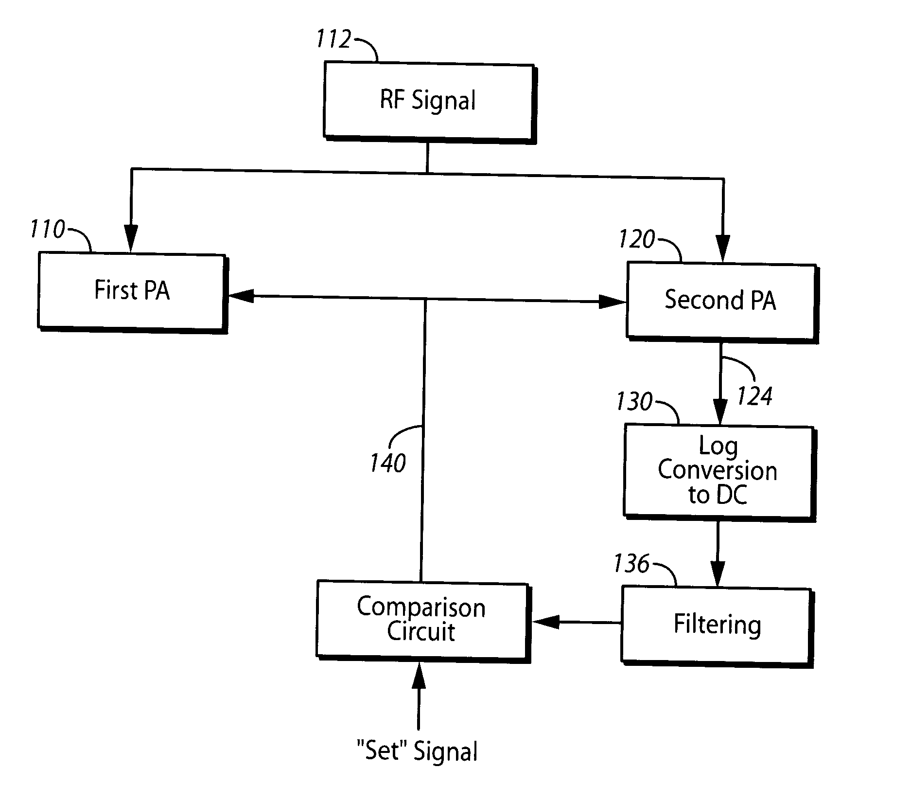
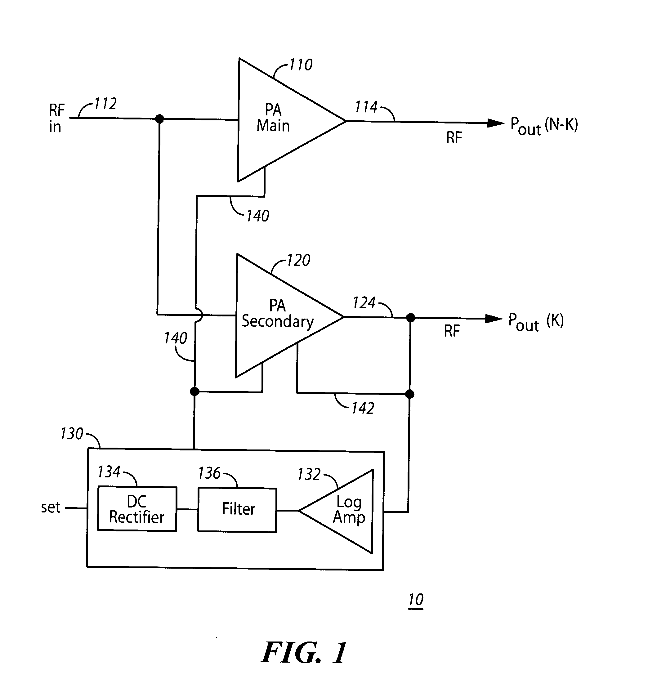
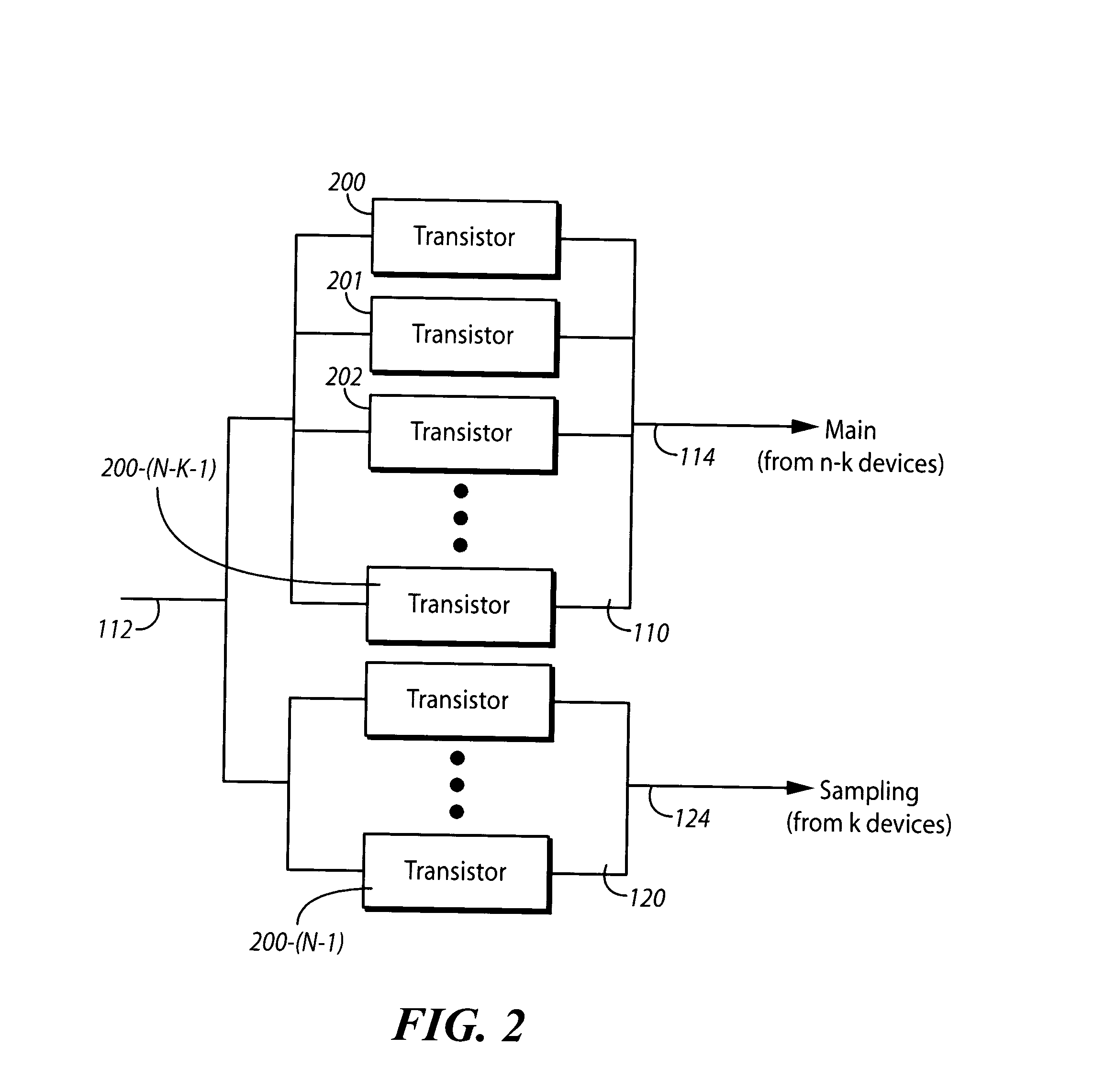
The present invention relates to an efficient technique and structure for detecting transmit power associated with a power amplifier. In accordance with certain embodiments of the invention, a circuit contains an array of coupled transistors in two power amplifiers, all resident on a single semiconductor die, and a log-detector circuit. The main power amplifier contains the larger array of transistors to amplify the radio frequency signal for feeding to an antenna, and a secondary power amp contains a smaller array of transistors to provide a scaled output that is proportional to the amplified radio frequency signal and is used to control the main power amp. The log-detector circuit converts the signal from the secondary power amp to a full-wave rectified log-linear DC signal that is logarithmically proportional to a controlling signal. The DC signal output from the log-detector circuit is fed to the main power amp to control it. While this invention is susceptible of embodiment in...


PUM


Abstract

A circuit for detecting the amount of radio frequency power provided by an amplifier. The circuit contains an array of coupled transistors in two power amplifiers, and a log-detector circuit, all resident on a single semiconductor die. The main power amplifier contains the larger array of transistors to amplify the radio frequency signal for feeding to an antenna, and a secondary power amplifier contains a smaller array of transistors to provide a scaled output that is proportional to the amplified radio frequency signal and is used to control the main power amplifier. The log-detector circuit converts the signal from the secondary power amplifier to a full-wave rectified log-linear DC signal that is logarithmically proportional to the controlling signal. The DC signal output from the log-detector circuit is fed to the main power amp to control it.

Description

FIELD OF THE INVENTION This invention relates generally to radio frequency power amplifiers. More particularly, this invention relates to control circuitry for determining and controlling the output power provided by power amplifiers. BACKGROUND OF THE INVENTION Modern mobile wireless devices such as cellular telephones, portable radios, personal communication devices, and two-way pagers operate on battery power, and in the transmit mode they can consume a significant amount of battery capacity. Although newer battery chemistries have increased the capacity of rechargeable batteries, the physical size of these electronic devices and their associated batteries continues to shrink, making battery power a precious commodity that is expensive and at times in short supply. These mobile devices generally require that a specified radio frequency (RF) output power be delivered to a radiating antenna, so rather than delivering a constantly high power at all times, some systems dynamically ...

Claims


Application Information

Patent Timeline
10 Feb 2005
Publication
US20050032499A1
IPC
H03G3/30; H04B1/04
CPC
H04B2001/0416; H03G3/3042
Inventors
CHO, JIN WOOK