Tool changing device and tool cleaning method

a tool and tool cleaning technology, applied in the field of tool changing devices and tool cleaning methods, can solve the problems of affecting machining accuracy, deteriorating machining accuracy, and holder not being properly fitted to the spindl

Inactive Publication Date: 2005-02-10
FANUC LTD
View PDF7 Cites 10 Cited by
  • Summary
  • Abstract
  • Description
  • Claims
  • Application Information

AI Technical Summary

Benefits of technology

[0017] By subjecting the tools held by the turret or magazine to the coolant or air spouted from the nozzle while the turret or magazine is rotated, the foreign matter such as swarf adhered to the tapered portion and / or the flange portion of the tools in a standby state is securely removed. This results in more reliable removal of the foreign matter from the tapered portion and / or the flange portion of the tool as contact faces to be in contact with a spindle of the machine tool.

Problems solved by technology

If foreign matter, such as swarf, is adhered to a contact surface of the tool with the spindle, a tool holder may not be properly fitted to the spindle, which affects the machining accuracy.
If the tool is attached to the spindle and used with the foreign matter adhered thereto, there occur problems that the machining accuracy is deteriorated and that the spindle and the tapered and flange portions of the tool get scratches.
Even the cleaning process using the coolant or the like cannot completely remove such swarf.
Likewise, in case of dry machining or machining using air, the amount of swarf adhered to the tool in the turret or magazine is increased by static electricity and the like, so that it is impossible to completely remove the swarf by performing the cleaning process using air.

Method used


Image

  • Tool changing device and tool cleaning method
  • Tool changing device and tool cleaning method
  • Tool changing device and tool cleaning method

Examples


first embodiment

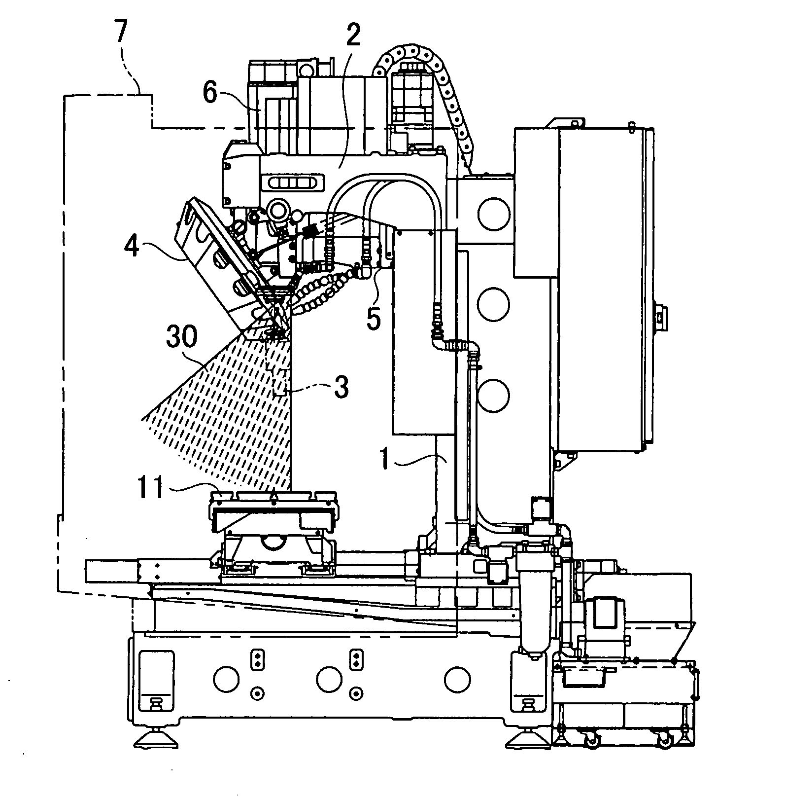
[0023]FIG. 1a is an elevation view showing a machine tool employing a tool changing device of the present invention when viewed with a front cover 7 removed. FIG. 1b is a side view of the machine tool.

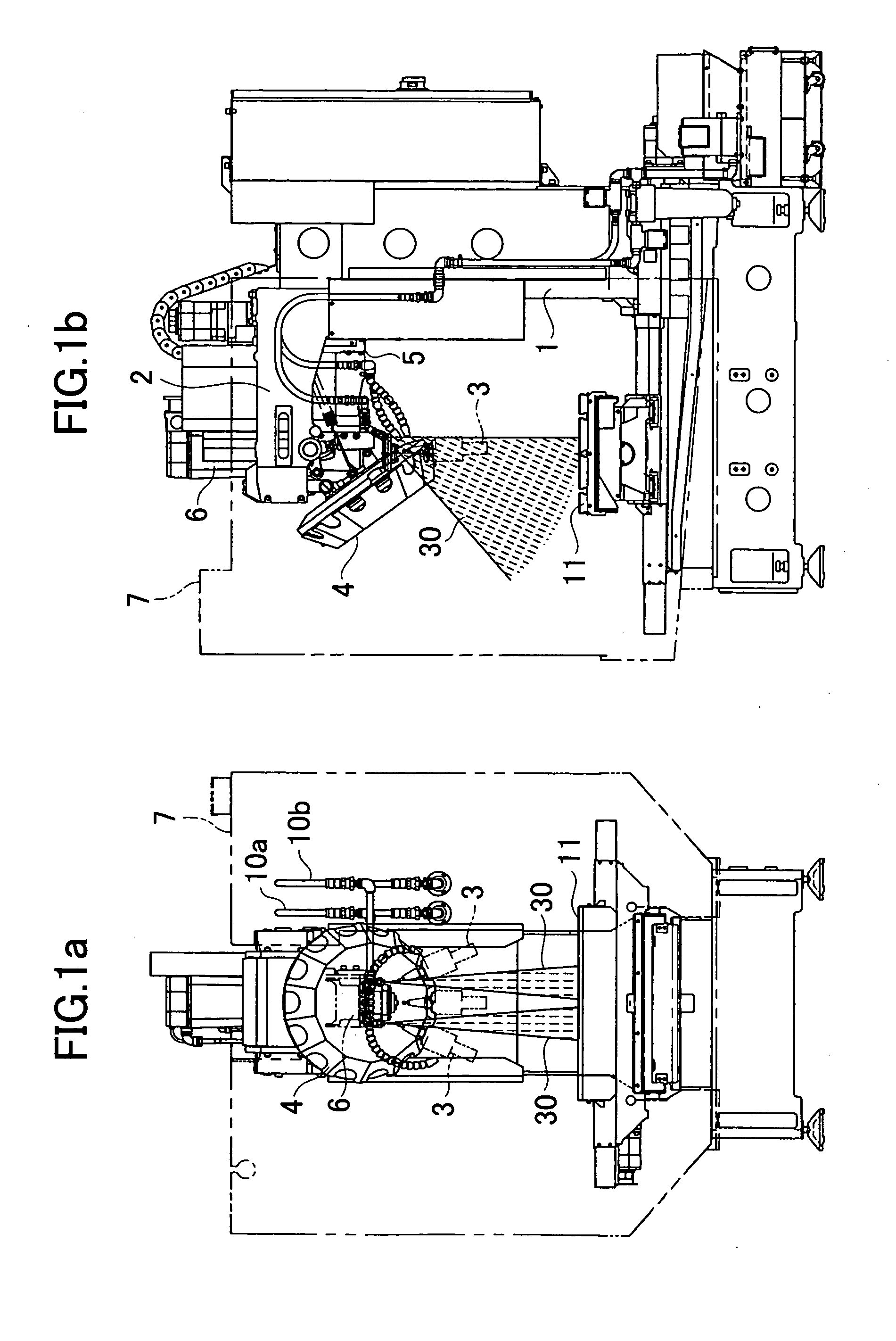
[0024]FIG. 2a is an enlarged front view and an enlarged side view of the tool changing device shown in FIGS. 1a and 1b.

[0025] An arm member 2 is mounted on a column 1 of the machine tool to extend horizontally, and a turret 4 for holding tools 3 is rotatably attached to the arm member 2. A spindle head 5 is supported by the column 1 to be vertically movable and a spindle 6 is provided at the spindle head 5. A tool 3 is fitted to the spindle 6 for cutting a workpiece placed on a table 11. Tool cooling nozzles 8a, 8b for supplying coolant to a machining area to cool the tool are fixed to the spindle head 5. In changing the tool 3, the spindle 6 is raised to detach the tool 3 from the spindle 6 and the turret 4 holds the detached tool 3. Thereafter, the turret 4 is rotated to select a to...

second embodiment

[0034] the two tool cleaning nozzles 9a, 9b are fixed to the column 1 of the machine tool, and arranged on the both sides of the spindle 6 with the spindle 6 in-between, to thereby spout the coolant 30 toward regions where the tapered portion 3a and flange portion 3b of the tool 3 held by the turret 4 pass.

[0035] Also in the second embodiment, when the turret 4 is rotated for tool selection or the like, the tool cleaning nozzles 9a, 9b spout the coolant 30 supplied through the coolant supply pipe 10b, and the tool 3 held by the turret 4 passes through the spouted coolant 30, thereby cleaning the tool 3 held by the turret 4. It would be obvious that the selected tool 3 also passes through the spouted coolant 30. Therefore, even right before the tool is fixed to the spindle, the spouted coolant 30 cleans the tapered portion 3a and flange portion 3b of the tool and removes foreign matter, such as swarf.

[0036]FIGS. 4a and 4b are explanatory views showing a substantial part of a third ...

third embodiment

[0037] Likewise in the third embodiment, during the tool selection, the coolant 30 is spouted from the tool cleaning nozzles 9a, 9b. Moreover, sprockets 22 are driven to rotate the chains 21, and the pots 23 and the tools 3 accommodated in the corresponding pots 23 are then rotated, thereby carrying out the tool-selecting operation. At this point, the tools 3 pass through the coolant 30 spouted from the tool cleaning nozzles 9a, 9b. This cleans the tapered portions 3a and flange portions 3b of the tools 3, which are the contact faces to be in contact with the spindle 6. Consequently, the tools 3 accommodated in the magazine 20 are cleaned whenever the tool selection is performed, and whenever the chains 21 are rotated.

[0038]FIGS. 5a through 5h show machining fluid-spouting shapes according to various coolant-spouting shapes of the tool cleaning nozzles 9a, 9b, which are employed in the first, second and third embodiments. FIGS. 5a and 5b each show a tool cleaning nozzle that spouts ...


PUM

PropertyMeasurementUnit
areaaaaaaaaaaa
viscosityaaaaaaaaaa
shapeaaaaaaaaaa

Abstract

A tool changing device and a tool cleaning method capable of surely removing foreign matter such as swarf adhered to tapered portions and/or flange portions of tools, which serve as contact faces to be in contact with a spindle. There is arranged tool cleaning nozzles for spouting coolant on both sides of the spindle in the rotating position of a turret. The tool cleaning nozzle has a position and a posture such that the coolant spouted from the nozzle hits against the tapered portions and/or the flange portions of the tools held by the turret. The coolant is spouted from the tool cleaning nozzle with the rotation of the turret at the time of tool selection. Each time the turret rotates, the tapered portions and/or the flange portions of the tools held by the turret are cleaned by the coolant. Even if foreign matter, such as swarf, is adhered to the standby tools held by the turret, it is possible to surely remove the foreign matter, such as swarf, since the tools are cleaned during the rotation of the turret.

Description

BACKGROUND OF THE INVENTION [0001] 1. Field of the Invention [0002] The present invention relates to a tool changing device for a machine tool and a method of cleaning tools held by a turret or magazine of the tool changing device. [0003] 2. Description of the Related Art [0004] In changing a tool of a machine tool, machining accuracy of a workpiece is maintained by properly fitting and attaching the tool to a spindle of the machine tool. In a machine tool having a tool changing device, however, tools held by a turret or a magazine are arranged close to a machining area where a workpiece is cut. Therefore, there is a high possibility that swarf produced by cutting of a workpiece is adhered to the tools held by the turret or the magazine. If foreign matter, such as swarf, is adhered to a contact surface of the tool with the spindle, a tool holder may not be properly fitted to the spindle, which affects the machining accuracy. For this reason, the method generally employed is one in w...

Claims


Application Information

Patent Timeline
Patent Type & Authority Applications(United States)
IPC IPC(8): B23Q3/155B23Q11/00
CPCB23Q3/1552B23Q11/005Y10T483/10Y10T29/5154Y10T483/1891Y10T483/1755Y10T483/15B23Q3/15534
Inventor SATO, NAOKIFUJIMOTO, AKIHIKO
Owner FANUC LTD
Why Eureka
Try Eureka