Apparatus and method for accelerated exhaust system component heating

a technology of exhaust system and component heating, applied in mechanical equipment, machines/engines, electric control, etc., can solve the problems of inefficient cooling of catalysts used to treat exhaust gases at lower temperatures, excessively high engine speed, and high cost of systems, so as to improve cold start emissions and reduce warm-up time

Inactive Publication Date: 2005-02-17
GM GLOBAL TECH OPERATIONS LLC
View PDF14 Cites 44 Cited by
  • Summary
  • Abstract
  • Description
  • Claims
  • Application Information

AI Technical Summary

Benefits of technology

[0007] Therefore, what is needed is a way to effect a reduction in warm-up time for certain exhaust components so that improvements to cold start emissions can be realized. Preferably, solutions will not come with significant expense, mass or reliability issues. Additionally, a solution that provides for normal electrical system operation, including protective regulation thereof, is also desired. Moreover, incorporated utilization of the otherwise wasted, dissipated energy in advancing such solutions is generally desirable.

Problems solved by technology

It is known in the area of internal combustion engine emissions control that the time during which an engine is running prior to the certain emissions control components reaching critical operating temperatures is a significant contributor to overall hydrocarbon tailpipe emissions.
This is generally true because the catalysts used to treat exhaust gases are inefficient at lower temperatures and because the exhaust gas sensors used for closing the loop on air-fuel ratio have not yet reached their operating temperature and thus cannot be used.
Such systems come with expense, mass and reliability penalties.
However, excessively high engine speeds may be objectionable to a vehicle operator.
However, modern engines have limited spark retard authority as too much retard contributes to combustion instability.
It is also known that increasing the engine load and thus the amount of fuel consumed per combustion cycle also increases the heat output to the exhaust.
However, such an arrangement suggests energy dissipation internal to the machine, which may mean unregulated operation and damaging voltage / current levels.
This represents a potentially damaging or wasteful energy dump.
Such systems demand significant electrical energy to effect rapid heating.

Method used


Image

  • Apparatus and method for accelerated exhaust system component heating
  • Apparatus and method for accelerated exhaust system component heating
  • Apparatus and method for accelerated exhaust system component heating

Examples


Embodiment Construction

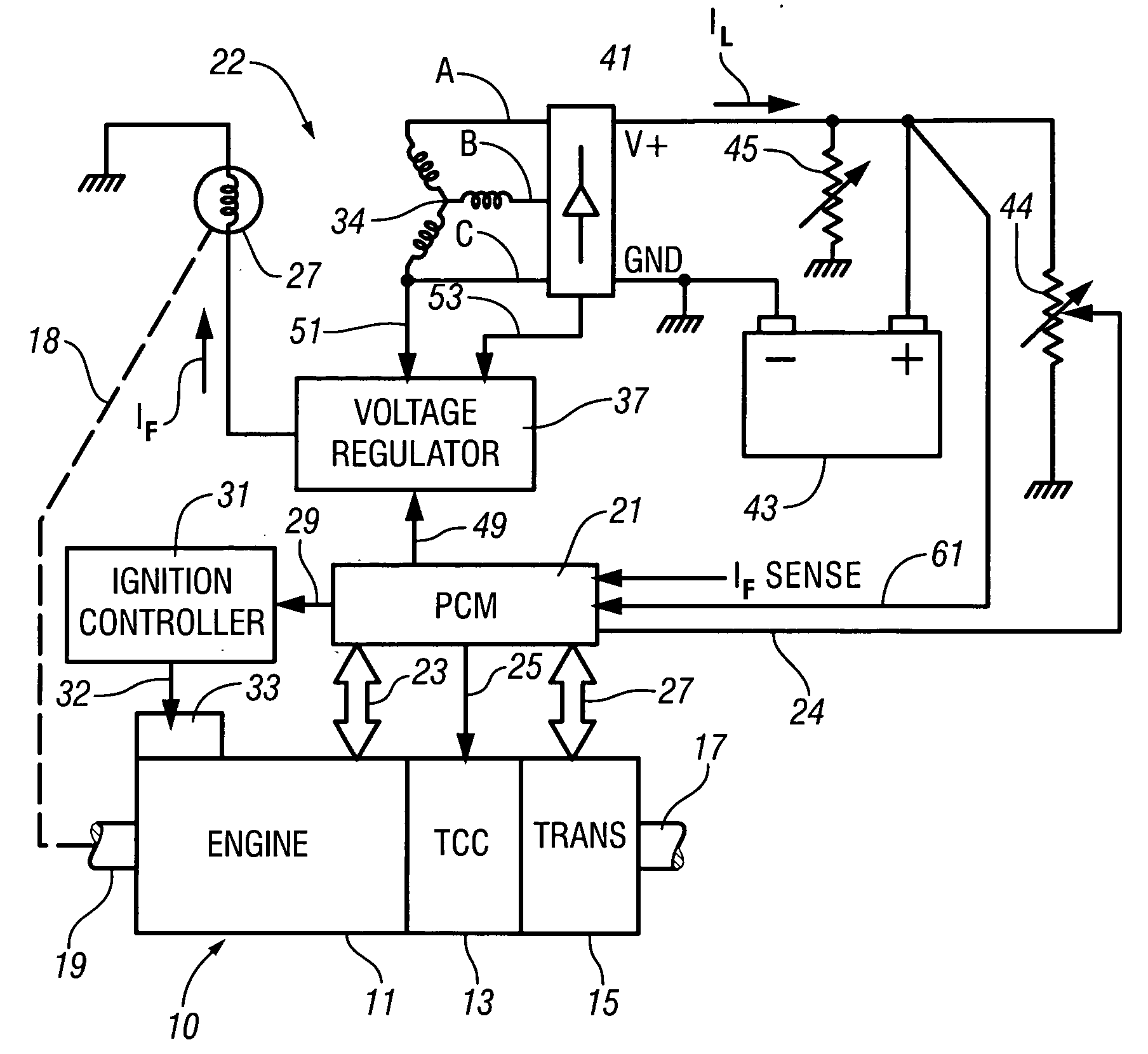
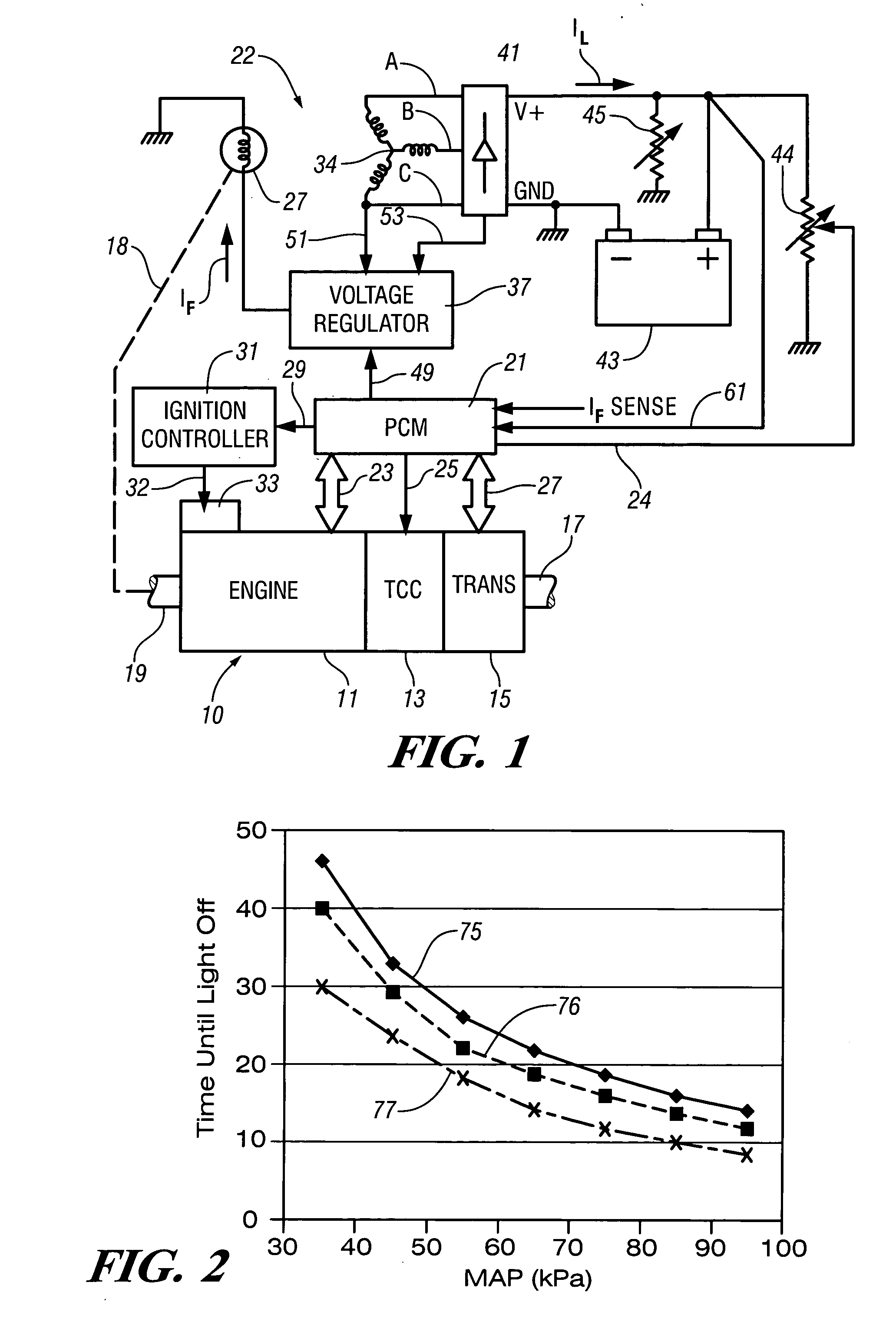
[0017] An exemplary automotive environment in which certain preferred embodiments of the present invention may be practiced is generally illustrated and described with respect to FIG. 1. A motor vehicle includes a powertrain generally labeled 10 and more specifically comprising an internal combustion engine 11 coupled to a multi-ratio automatic transmission 15 through an engaged torque converter clutch 13. Transmission 15 has an output shaft 17 which in turn is mechanically coupled to at least one drive wheel through differential and final drive gear sets (not shown). Engine 11 also has an accessory drive shaft 19 for driving a plurality of engine driven accessories by way of a pulley and belt system (not shown). Such engine powered accessories may include, for example, air conditioning compressors, intake air superchargers and vehicle electrical system generators.

[0018] Engine and transmission control functions are implemented by way of a computer based powertrain control module (...


PUM


Abstract

Accelerated heating of automotive exhaust system components is effected by controlling the application of supplemental electrical loads to the vehicle electrical system thereby increasing engine load and increasing exhaust heat. Alternative strategies are disclosed for implementing the invention through control of electrical and engine management system parameters.

Description

TECHNICAL FIELD [0001] The present invention is related to managing cold start emissions from automobiles. More particularly, the invention facilitates a reduction in the time it takes for the exhaust system components to warm-up during cold starts. BACKGROUND OF THE INVENTION [0002] It is known in the area of internal combustion engine emissions control that the time during which an engine is running prior to the certain emissions control components reaching critical operating temperatures is a significant contributor to overall hydrocarbon tailpipe emissions. This is generally true because the catalysts used to treat exhaust gases are inefficient at lower temperatures and because the exhaust gas sensors used for closing the loop on air-fuel ratio have not yet reached their operating temperature and thus cannot be used. Additionally, the engine is typically calibrated with rich air-fuel ratios to avoid misfires and partial burns, which further contributes to the hydrocarbon emissio...

Claims


Application Information

Patent Timeline
Patent Type & Authority Applications(United States)
IPC IPC(8): F01N3/20F02D37/02F02D41/02
CPCF01N3/2006F02D37/02Y02T10/26F02D2041/026F02D41/0245Y02A50/20Y02T10/12
Inventor FRIEDEN, DOUGLAS E.CLEARY, DAVID J.NAIK, SANJEEV MANUBHAI
Owner GM GLOBAL TECH OPERATIONS LLC
Why Eureka
Try Eureka