Monolithic tube sheet and method of manufacture

a technology of monolithic tubes and tubes, which is applied in the direction of heat exchanger casings, heat exchange apparatus, light and heating equipment, etc., can solve the problems of further reducing steps in the assembly of heat exchangers, and achieves the effects of preventing fluid leakage, minimizing fluid leakage, and vastly simplifying the manufacturing and assembly of tube sheets

Inactive Publication Date: 2005-02-17
GRAHAM ROBERT G
View PDF14 Cites 22 Cited by
  • Summary
  • Abstract
  • Description
  • Claims
  • Application Information

AI Technical Summary

Benefits of technology

[0010] By forming the ceramic tube sheet as a unitary block or monolith, the fluid leakage between joined ceramic tiles, as in the prior art is eliminated. Fabrication and assembly of the tube sheet is vastly simplified since multiple small tiles do not have to be assembled and cemented together. Additionally, since the same form may be used to create both tube sheets used within a single heat exchanger, the alignment of ceramic tubes between tube sheet pairs is easily accomplished. This precise alignment of the tubes between the tube sheet pairs is critical since it prevents problems with tube assembly, and insures that the tubes are equally loaded during operation.
[0011] The monolithic refractory ceramic tube sheet is described in combination with an adjustable, articulating, sealing plug. The plug is provided in a length such that it extends across the thickness of the tube sheet, and the exterior is provided with threads adjacent the outer (dome side) face of the tube sheet. These threads engage mating threads formed in the tube sheet through channels, allowing the position of the plug to be longitudinally adjusted within the through channel. This ability to adjust the longitudinal position of the plug allows compensation for variations in tube length, and ensures that each tube can be equally loaded at assembly. Additionally, the plug can be completely removed from the outer face of the inventive tube sheet, allowing replacement of a ceramic tube from the dome-side of tube sheet, or outside the heat exchanger itself Adjacent to the inner (tube side) face of the tube sheet, the plug is provided with an articulated, sealing joint which receives and supports the terminal ends of a ceramic tube. This joint allows rotational motions of the terminal end of the tube, and prevents fluid leakage within the through channel.
[0012] A method for forming the monolithic tube sheet is provided. Casting a refractory ceramic in a mold, where portions of the mold comprise the housing of the heat exchanger, forms the monolithic tube sheet. Thus, the tube sheet is cast in place within the housing. This is advantageous since the tube sheet takes on the form of the shell, minimizing fluid leakage between the casting and the shelf wall. Additionally, this step further reduces steps in the assembly of the heat exchanger. Precisely formed negatives are used to form through channels and vacancies within the tube sheet, which are carefully and precisely placed within the mold. This precision allows uniform and flush formation of openings that receive the ceramic tubes therein, which is critical so that when assembled and in use each ceramic tube can be equally loaded.

Problems solved by technology

Additionally, this step further reduces steps in the assembly of the heat exchanger.

Method used


Image

  • Monolithic tube sheet and method of manufacture
  • Monolithic tube sheet and method of manufacture
  • Monolithic tube sheet and method of manufacture

Examples


Embodiment Construction

[0025] Monolithic Tube Sheet

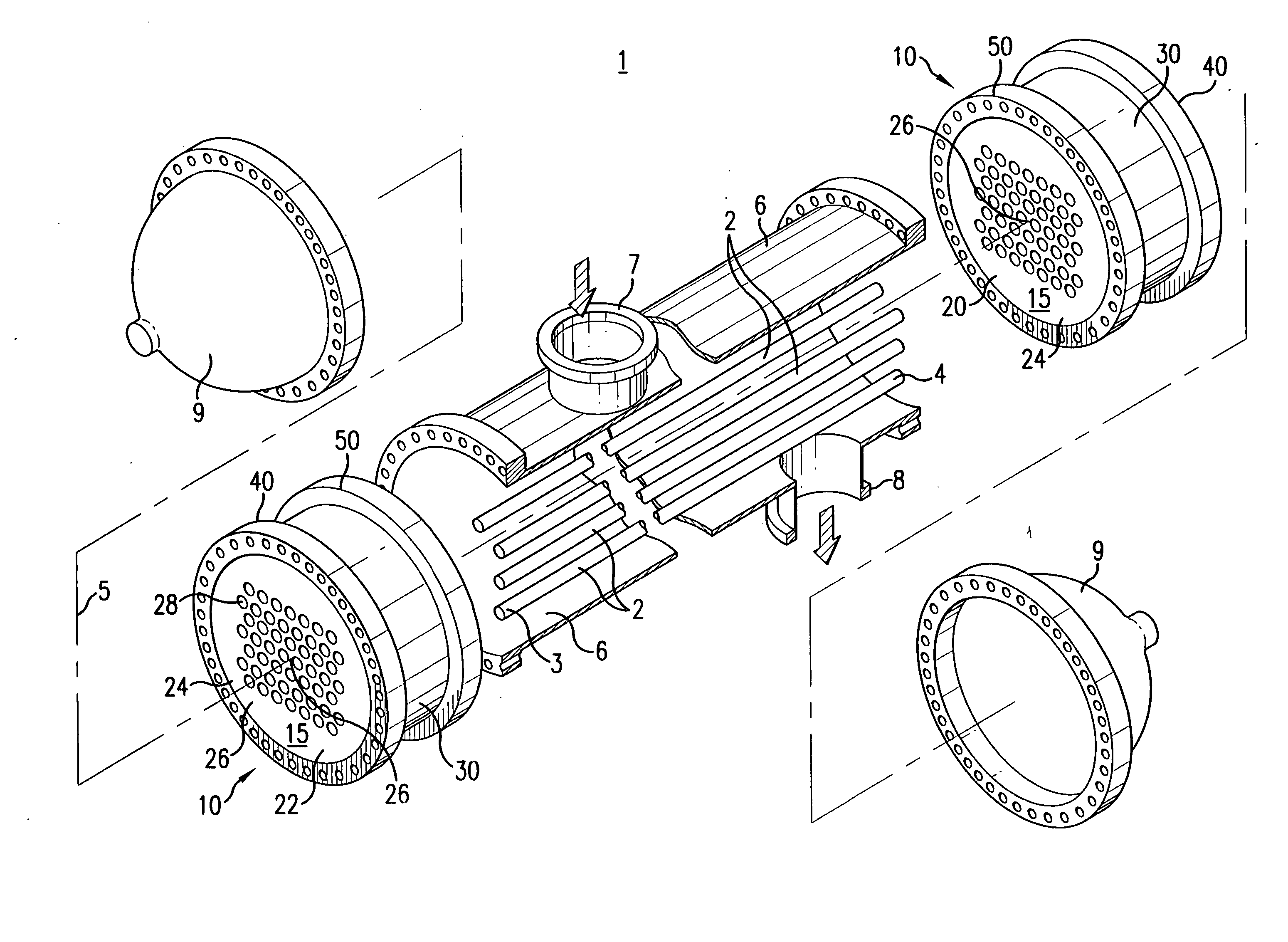
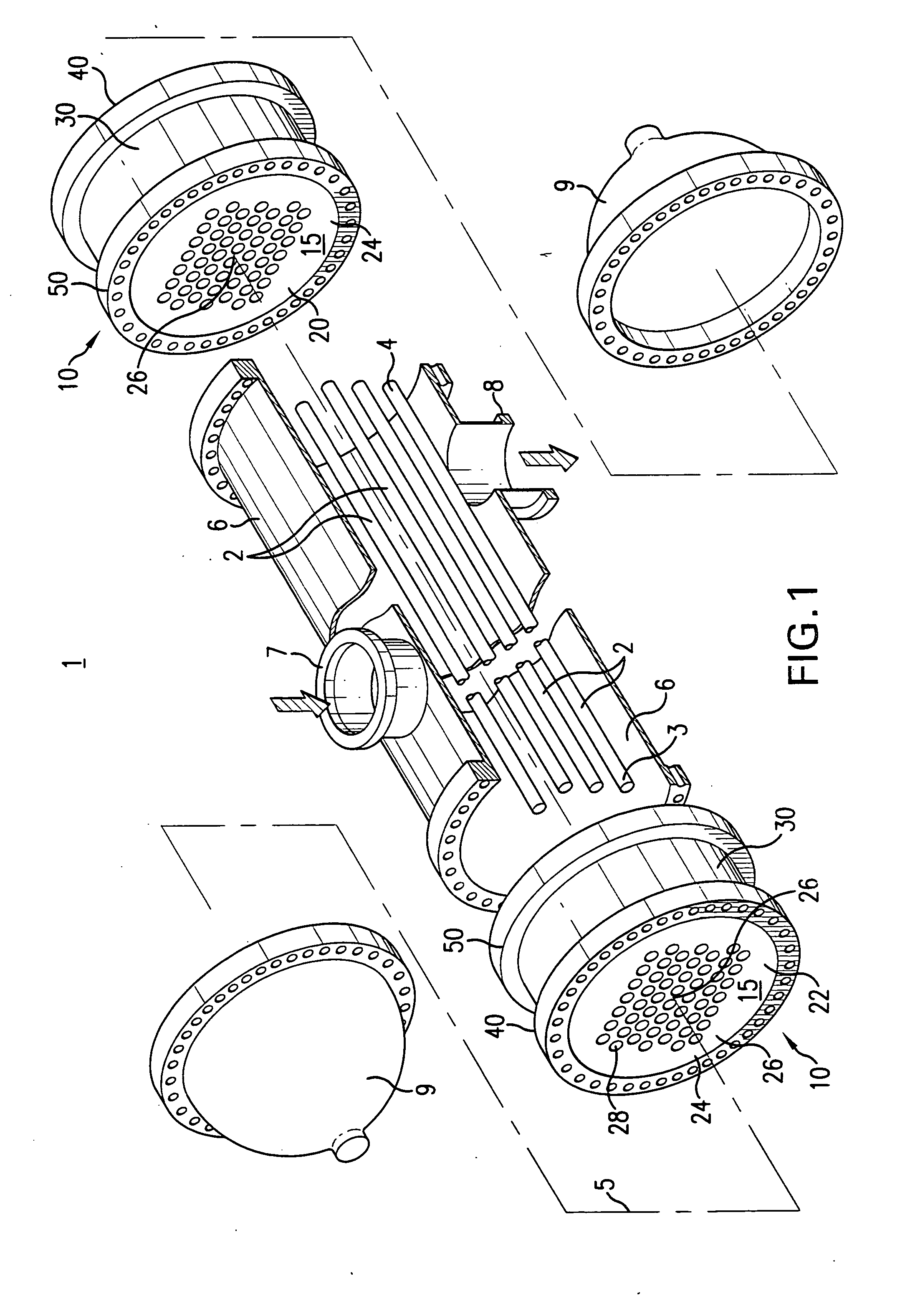
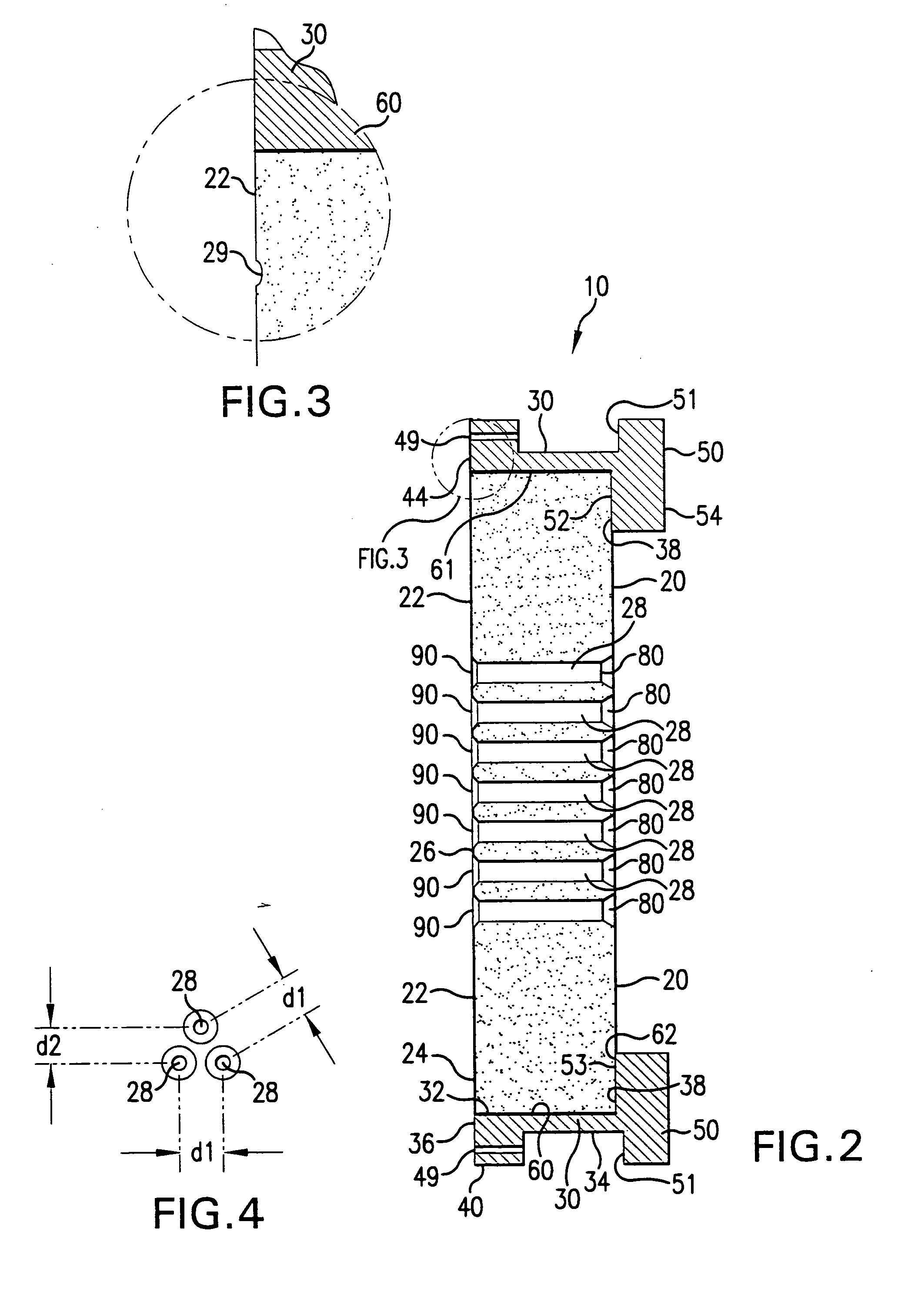
[0026] Referring to FIGS. 1 and 2, the inventive tube sheet 10 will now be described in detail. Tube sheet 10 is a monolithic refractory ceramic plate for use in all-ceramic air-to-air indirect heat exchangers. These ceramic heat exchangers are used in medium to high temperature, and high pressure applications where metal components are unsuitable. One such application is the extraction of thermal energy from industrial waste gases for use in heating clean ambient air it is, however, within the scope of this invention to employ the inventive concept in other severe environment applications, which include, but are not limited to, those found in the power and aerospace industries.

[0027] The indirect heat exchanger of this invention allows efficient heat transfer from one fluid to another across a tube wall. A first fluid is passed through an array of parallel, elongate tubes such that it flows within the tube interior spaces. The tube array is enclosed wi...


PUM

PropertyMeasurementUnit
pressuresaaaaaaaaaa
temperatureaaaaaaaaaa
pressuresaaaaaaaaaa

Abstract

A monolithic refractory ceramic tube sheet for use in all-ceramic air-to-air indirect heat exchangers, the heat exchanger used in medium to high temperature, and high pressure applications. A method for forming the monolithic tube sheet includes-casting a refractory ceramic in a mold, where portions of the mold comprise the housing of the heat exchanger. Precisely formed negatives are used to form through channels and vacancies within the tube sheet, which are precisely positioned within the mold allowing uniform and flush formation of openings that receive the ceramic tubes therein. The same mold is used to provide both tube sheets of a tube sheet pair allowing accurate alignment of tubes within the exchanger vessel resulting in ease of assembly and equal loading of tubes when in use.

Description

BACKGROUND OF THE INVENTION [0001] Heat exchangers are devices built for efficient heat transfer from one fluid to another. Conventional heat exchangers accomplish this heat transfer using a wide variety of interfaces and fluids. This invention is concerned with indirect heat transfer between two fluids of different temperatures across a dividing wall. More specifically, this invention is concerned with an indirect air-to-air heat exchanger, for use in high temperature, high pressure applications, which uses an array of parallel tubes extending lengthwise within an elongate hollow vessel. The array of tubes is supported at each end of the vessel using a tube sheet. Tube sheets are used to receive the terminal ends of the tubes such that the tubes extend in a direction normal to the tube sheet face. The terminal ends of the tubes are seated within through channels in the tube sheet that allows fluid to pass between the interior of the tube and the opposing side of the tube sheet. A h...

Claims


Application Information

Patent Timeline
Patent Type & Authority Applications(United States)
IPC IPC(8): F28F9/02F28F9/06F28F9/10F28F21/04
CPCF28F9/02F28F21/04F28F9/10F28F9/06
Inventor GRAHAM, ROBERT G.GOSKI, DANAESLICK, HERMAN L.DISAIA, ANTHONY S.BRENNEMAN, RONALD G.
Owner GRAHAM ROBERT G
Why Eureka
Try Eureka