Brake apparatus having automatic clearance adjusting mechanism with overadjustment preventer

a technology of automatic adjustment and preventer, which is applied in the direction of slack adjusters, actuators, braking elements, etc., can solve the problems of laborious work and layout, increased number of constituting parts, and complicated integration of these parts, so as to simplify the structure of the structure, facilitate integration, and reduce the effect of a number of parts

Inactive Publication Date: 2005-02-17
AKEBONO BRAKE IND CO LTD
View PDF7 Cites 34 Cited by
  • Summary
  • Abstract
  • Description
  • Claims
  • Application Information

AI Technical Summary

Benefits of technology

[0006] The present invention has been carried out to resolve the problems. It is an object of the present invention to provide a brake apparatus having an automatic clearance adjusting mechanism with overadjustment preventer, reducing a number of parts, simplifying a structure thereof and facilitating integration by hampering an adjusting nut from being pivoted both in preventing overadjustment and in operating a parking brake.

Problems solved by technology

Therefore, a number of constituting parts is increased and also integration thereof is complicated.
Therefore, working and layout thereof are laborious.

Method used


Image

  • Brake apparatus having automatic clearance adjusting mechanism with overadjustment preventer
  • Brake apparatus having automatic clearance adjusting mechanism with overadjustment preventer
  • Brake apparatus having automatic clearance adjusting mechanism with overadjustment preventer

Examples


first embodiment

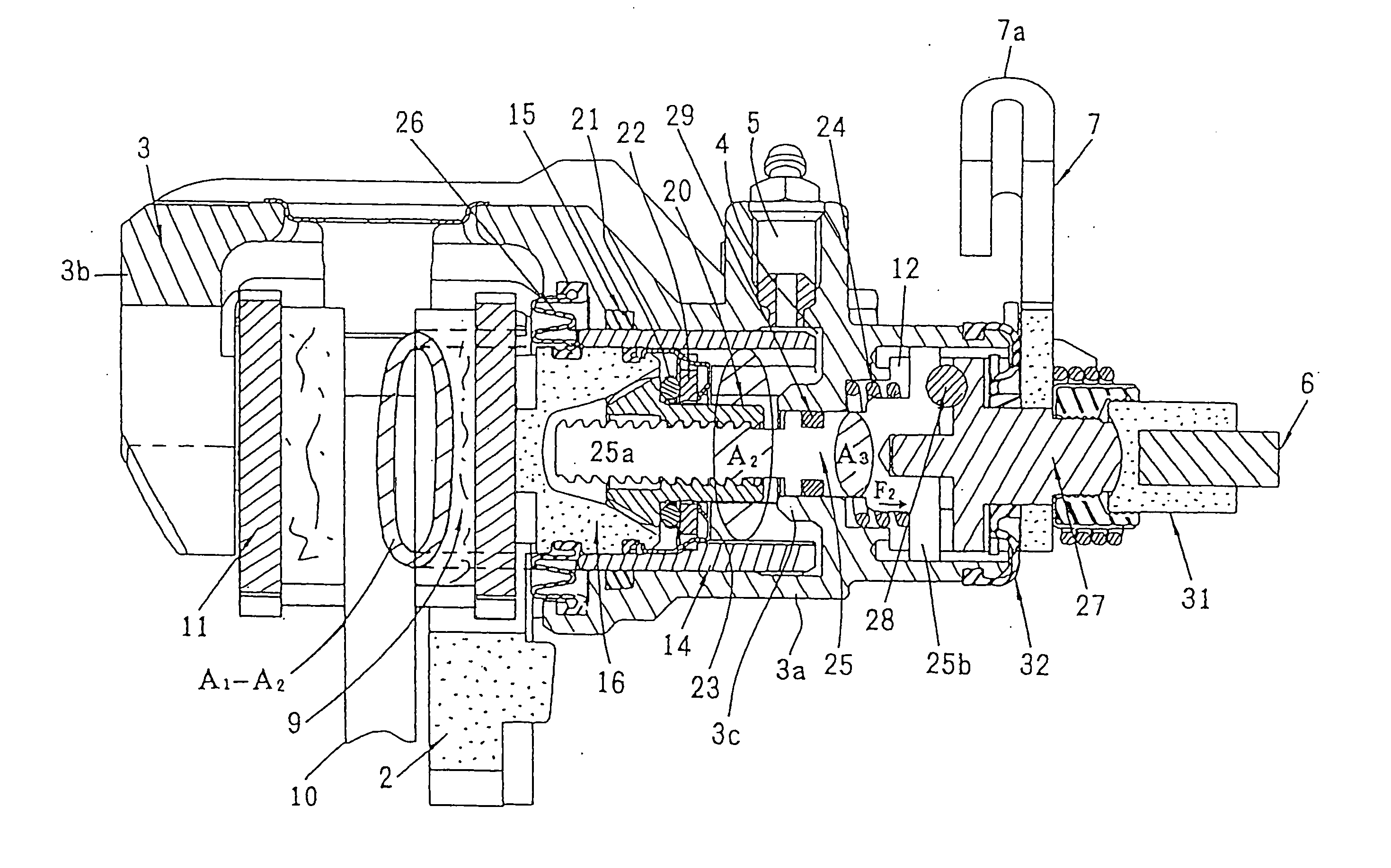
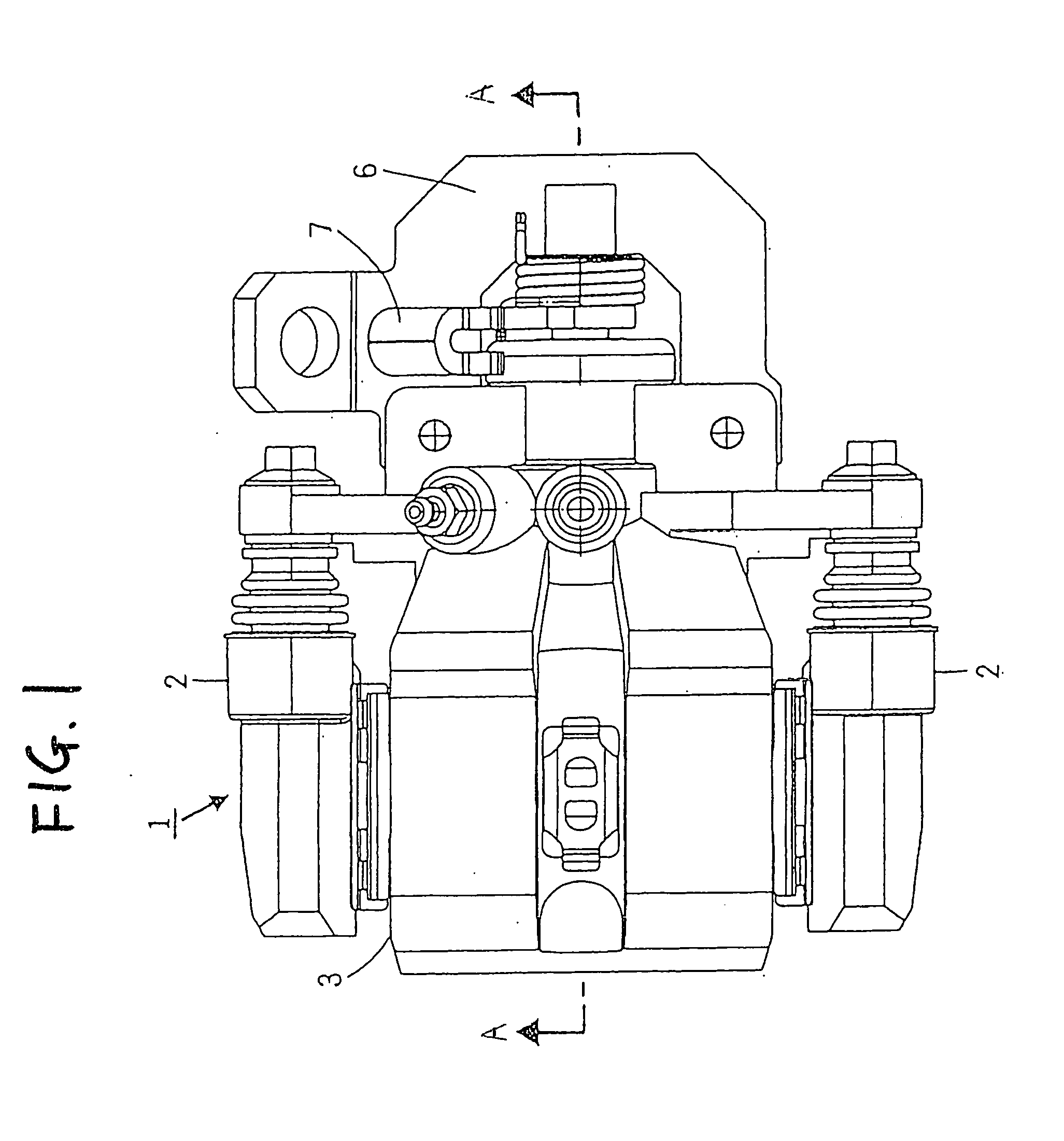
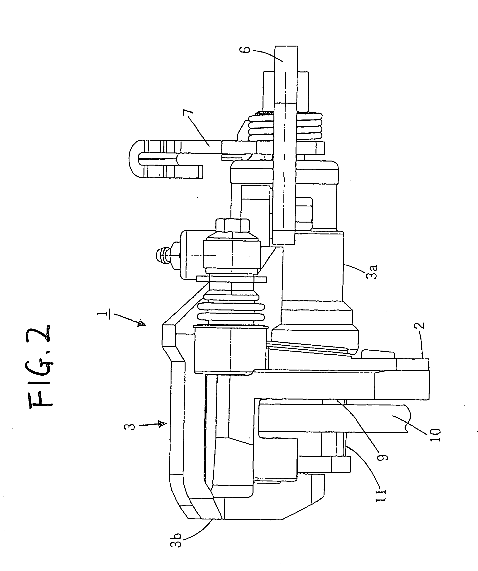
[0050] the invention will be explained in reference to FIG. 1 through FIG. 5C as follows. FIG. 1 is a plane view of a disc brake to which the invention is applied, FIG. 2 is a side view of the brake apparatus, FIG. 3 is a sectional view taken along a line A-A of FIG. 1, FIG. 4A is a disassembled view of an adjusting nut and a piston, FIG. 4B is a perspective view showing a state after integrating the adjusting nut to a plug piston to integrate and before fitting to insert into a ring piston, FIG. 5A is a sectional view showing a state of integrating the adjusting nut to the two pistons, and FIGS. 5B and 5C are partially enlarged views of FIG. 5A.

[0051] In FIG. 1 and FIG. 2, according to a disc brake 1, a caliper 3 is slidably supported by a support 2 fixed to a portion of a vehicle body. An inside of a cylinder portion 3a formed at the caliper 3 is formed with a cylinder chamber 4 for introducing a braking hydraulic pressure from a master cylinder via a hydraulic pressure introducin...

embodiment 1

[0090] As shown by FIG. 8A, a plug piston assembly 46A is integrated with the plug piston 16 and the adjusting nut 20 by a spring holder 43 and a structure of the spring holder 43 differs from that of the spring holder 23 of That is, the difference resides in that a first outer side claw portion 23A is formed with an engaging projected portion 23d.

[0091] Further, as shown by FIG. 8A, the first outer side claw portion 23A and the inner side claw portion 23B are provided with functions and structures the same as those of the spring holder of the first embodiment. The engaging claw 23a of the first outer side claw portion 23A is engaged with the groove 16a provided at the plug piston 16, the front end portion 23b of the inner side claw portion 23B is brought into contact with the bearing support plate 22 to press the bearing support plate 22 to the plug piston 16 to thereby integrally assemble the plug piston 16, the adjusting nut 20, the bearing 21, the bearing support plate 22 by t...


PUM


Abstract

A brake apparatus having an automatic clearance adjusting mechanism with an overadjustment preventer constituted such that a piston is constituted by a structure of being divided in a plug piston 16 and a ring piston 14. The plug piston 16 is integrated with an adjusting nut 20, a bearing 21, a bearing support plate 22 and a spring holder 23. An outer side claw portion 23a of the holder is locked by an outer side groove 16 of the plug piston. The plug piston 16 integrated with the respective parts is inserted to fit to the ring piston 14 to thereby prevent the outer side claw portion 23a of the holder from being detached.

Description

BACKGROUND OF THE INVENTION [0001] The present invention relates to a brake apparatus with a parking brake, that presses a friction member to a rotor by operating a piston provided at inside of a cylinder portion of a caliper, and has an automatic clearance adjusting mechanism with an overadjustment preventer, provided between the cylinder and the piston, for properly maintaining a clearance between the friction member and the rotor by the overadjustment preventing automatic clearance adjusting mechanism. [0002] As a brake apparatus having an automatic clearance adjusting mechanism with an overadjustment preventer of a background art, for example, JP-B-05-074732 is known. The brake apparatus of JP-B-05-074732 comprises a ring piston in which a piston provided at inside of a cylinder portion is slidable at the inside of the cylinder portion, and a plug piston that slides at the inside of the cylinder piston for pressing a friction member. In the brake apparatus, the automatic clearan...

Claims


Application Information

Patent Timeline
Patent Type & Authority Applications(United States)
IPC IPC(8): F16D65/56F16D65/14F16D65/18
CPCF16D65/18F16D65/567F16D2125/06F16D2121/14F16D2123/00F16D2121/02
Inventor MAEHARA, TOSHIFUMI
Owner AKEBONO BRAKE IND CO LTD
Why Eureka
Try Eureka