
Multiple battery system and network controlled multiple battery system

a battery system and battery technology, applied in the field of vehicle battery systems, can solve the problems of consuming a large amount of time for recharging a battery with known devices, and achieve the effects of improving safety and security, improving time to charge, and fast starting

Inactive Publication Date: 2005-02-17
RESERVE POWER CELL
View PDF29 Cites 51 Cited by
  • Summary
  • Abstract
  • Description
  • Claims
  • Application Information

AI Technical Summary

Benefits of technology

[0018] The myriad of advantages of having reliable, readily accessible auxiliary electrical power in the multiple battery system of the instant invention can easily be appreciated. It eliminates the need to jump-start the vehicle or, if the electrical system has failed, it allows the user to determine such a failure and try to reach some assistance while on the auxiliary battery. The instant invention also eliminates the danger of trying to jump-start an automobile, where there is the potential for electrical sparking and explosion. Additionally, by avoiding the need for a jump-start with the instant invention, both safety and security are improved, as there is no need to leave your vehicle to seek assistance or flag down strangers when the vehicle will not start. Improved time to charge is also an important further advantage of the instant invention. Re-charging a battery with known devices can take significant amounts of time, if it is even possible, for instance in situations where you are stuck on a lonely back road. However, the instant invention allows the user to quickly start and immediately begin recharging both a main and an at least one auxiliary battery. These and other objects of the invention are discussed further herein.

Problems solved by technology

Re-charging a battery with known devices can take significant amounts of time, if it is even possible, for instance in situations where you are stuck on a lonely back road.

Method used


Image

  • Multiple battery system and network controlled multiple battery system
  • Multiple battery system and network controlled multiple battery system
  • Multiple battery system and network controlled multiple battery system

Examples


Embodiment Construction

[0105] In the drawings depicted elements are not necessarily drawn to scale and alike and similar elements are designated by the same and similar reference numerals throughout the several figures.

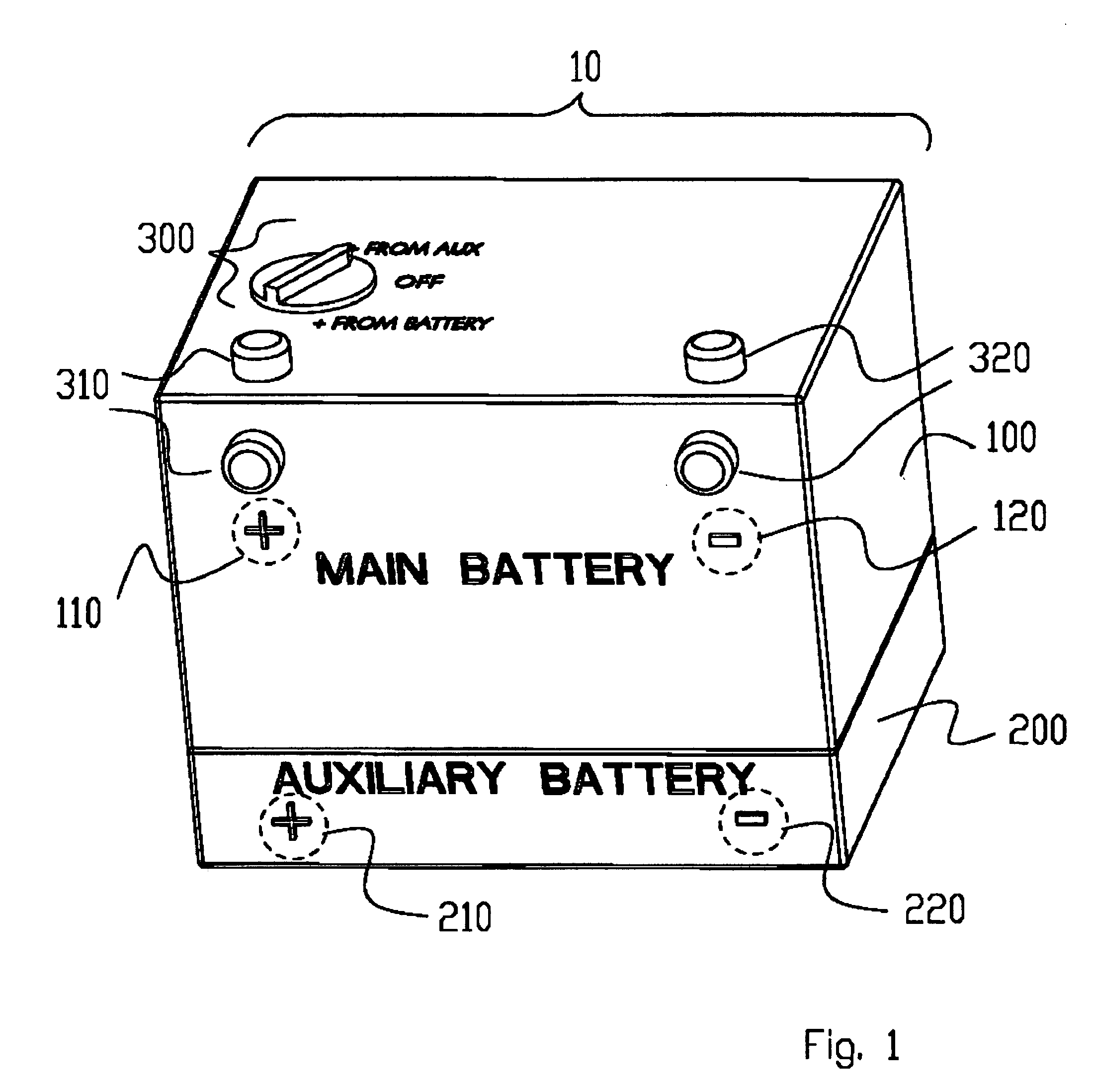
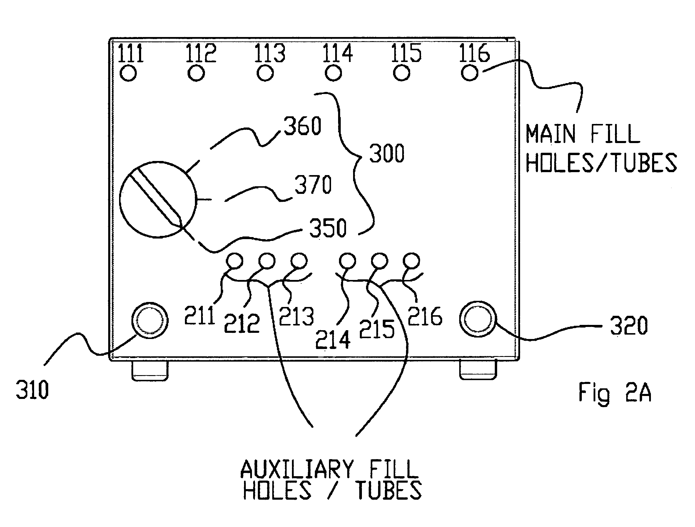
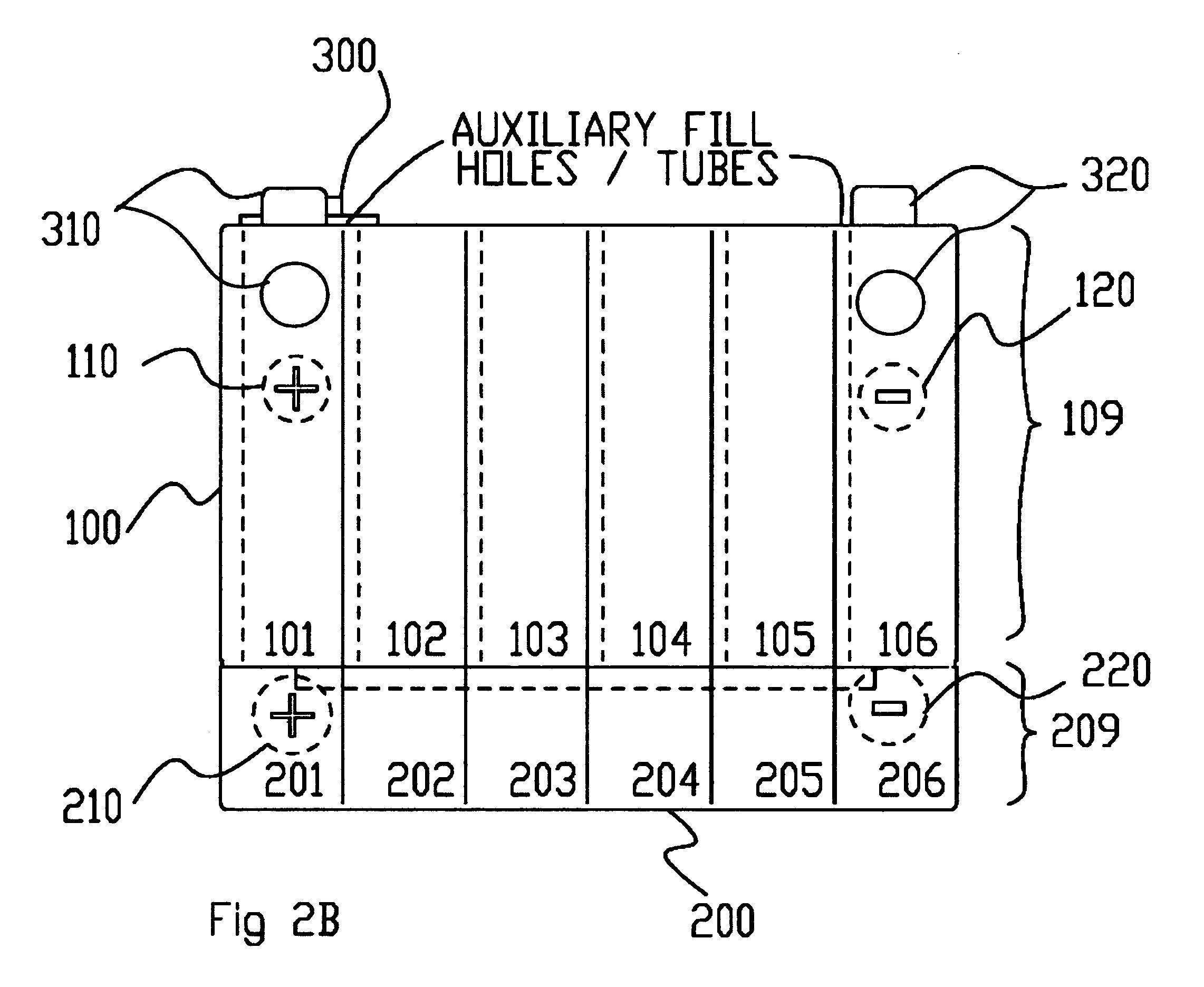
[0106] The instant invention is directed to a multiple battery system, having a main and an at least one auxiliary battery combination. In a non-limiting exemplary embodiment the instant invention is dimensioned to be a standard twelvebattery for auto, truck, marine and machinery applications meeting the original equipment manufacturers specifications. For instance, the non-limiting exemplary embodiment, as shown in FIGS. 1, 2a and 2b, comprises two twelve two-volt batteries in a single battery housing of conventional size and proportion. The main battery 100 and the standby, auxiliary, or backup battery 200 are contained in the housing 10, as further described herein below. Additional embodiments could include modifications to provide six-volt, twenty-four volt, thirty-six volt, forty-eig...


PUM

PropertyMeasurementUnit
coloraaaaaaaaaa
timeaaaaaaaaaa
electricalaaaaaaaaaa

Abstract

The instant invention is directed to a multiple battery system and network controlled multiple battery system. A main battery having a main positive output and a main negative output is also provided, together with an at least one auxiliary battery having an at least one auxiliary positive output and an at least one auxiliary negative output. A main electrical circuit having an at least one switching device is provided with at least two operating positions. The two operating positions selectively couple the main and at least one auxiliary battery to the common positive terminal. In the first of the at least two operating positions electrical charge is provided to both the main battery and the at least one auxiliary battery. A controller is also provided and coupled to the main electrical circuit and switches the at least one switching device based on input from an at least one sensor.

Description

CROSS REFERENCE TO RELATED APPLICATIONS [0001] This application is a Continuation-in-Part of pending U.S. patent application Ser. No. 10 / 604,703 entitled “Multiple Battery System and Auxiliary Battery Attachment System” filed on Aug. 11, 2003.BACKGROUND OF INVENTION [0002] The present invention relates, generally, to rechargeable battery systems including a main and an at least one auxiliary battery disposed for selective electrical communication, and more particularly to vehicle battery systems wherein the batteries of the battery system are configured within a housing having conventional external dimensions. Additionally the present invention includes an attachment for providing an at least one auxiliary battery attachment system to a conventional battery with circuitry for selectively engaging the main and at least one auxiliary battery and a method of detecting electrical faults in an electrical system coupled to the battery system. [0003] Almost every vehicle utilized today req...

Claims


Application Information

Patent Timeline
Patent Type & Authority Applications(United States)
IPC IPC(8): H01M10/04H01M10/12H01M10/42H01M50/541H01M50/574H02J7/00
CPCB60L3/0046H01M2/28H01M2/34H01M10/0413Y02T90/16H01M10/122H01M10/4207Y02E60/126Y02T10/7016H01M10/0445B60L58/18Y02E60/10Y02P70/50Y02T10/70H01M50/574
Inventor ELDER, DAVIDBRUNO, FRANK
Owner RESERVE POWER CELL
Learn More