
Method and apparatus for selection of scanning mode in dual pass encoding

a dual-pass encoding and scanning mode technology, applied in the field of dual-pass encoding systems, can solve the problems that frame/field motion prediction mode may not produce the best dct scan mode, and achieve the effect of improving encoding efficiency and improving picture quality

Inactive Publication Date: 2005-02-17
GENERAL INSTR CORP
View PDF6 Cites 53 Cited by
  • Summary
  • Abstract
  • Description
  • Claims
  • Application Information

AI Technical Summary

Benefits of technology

[0009] In one embodiment, the present invention discloses a system and method for adaptive selection of scanning modes based on the content of the input image sequence. Namely, content-adaptive scanning mode selection is able to assign DCT quantized coefficients in a more efficient scanning order, thereby reducing encoding bits and improving the picture quality.
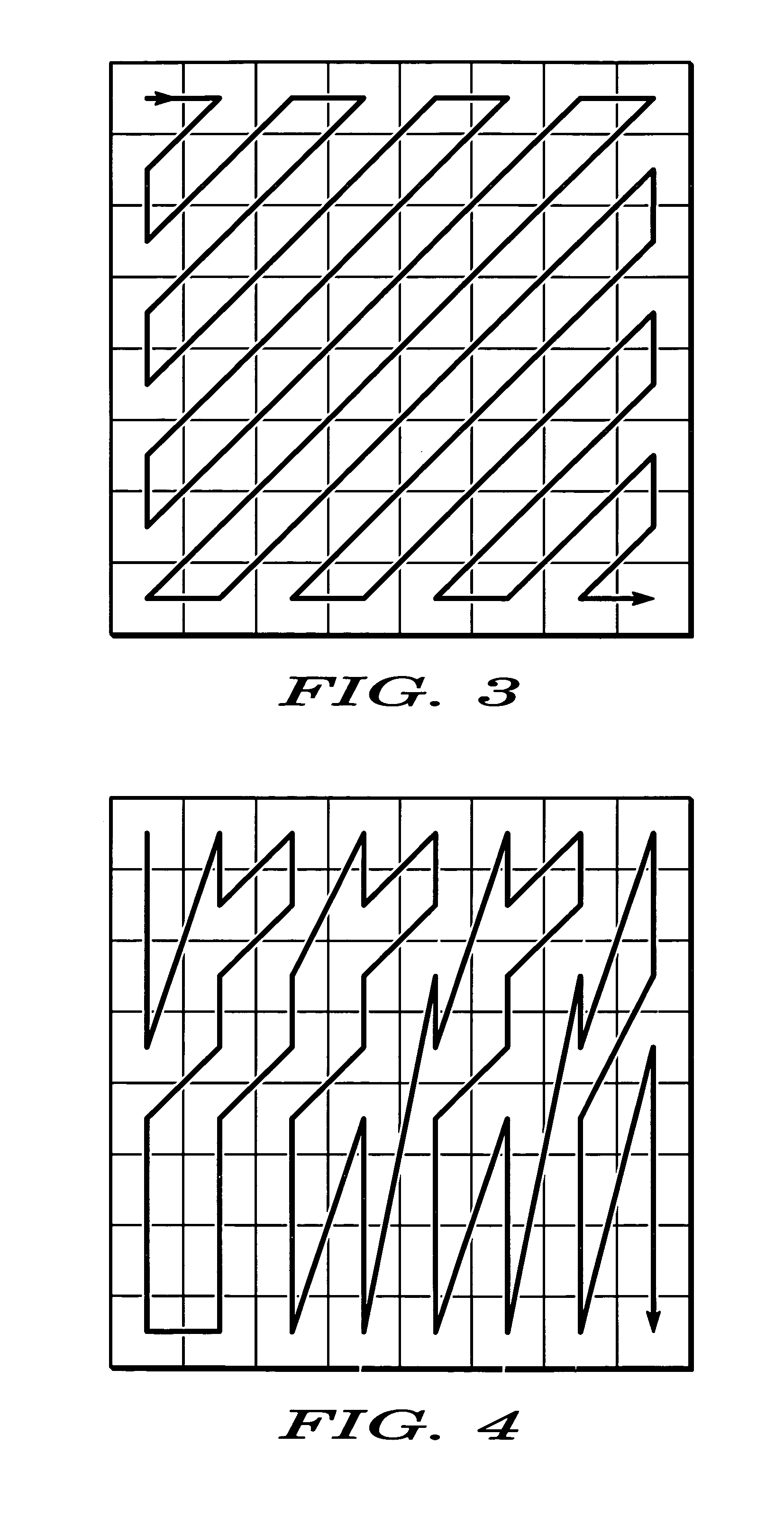
[0011] For example, the different portions may comprise slices of macroblocks, macroblocks, or subblocks within the macroblocks and so on. To illustrate, a picture having 480 rows can be divided into 30 slices of macroblocks. Odd slices of macroblocks will be encoded using a first scanning mode, e.g., the zigzag scanning mode, while even slices of macroblocks will be encoded using a second scanning mode, e.g., the alternative scanning mode. Once each frame is encoded, the encoder will be able to determine which scanning mode actually will be more efficient and / or will improve picture quality. This information is provided to a second encoder that will be able to adaptively select the proper scanning mode to actually encode the input image sequence. By using the appropriate DCT scan pattern, the second pass encoder is able to achieve better encoding efficiency on each individual frame or picture.

Problems solved by technology

However, sometimes the best frame / field motion prediction mode may not produce the best DCT scan mode.

Method used


Image

  • Method and apparatus for selection of scanning mode in dual pass encoding
  • Method and apparatus for selection of scanning mode in dual pass encoding
  • Method and apparatus for selection of scanning mode in dual pass encoding

Examples


Embodiment Construction

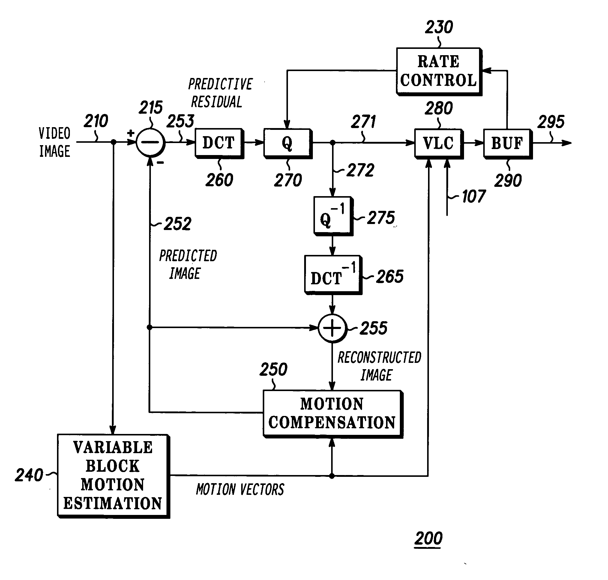
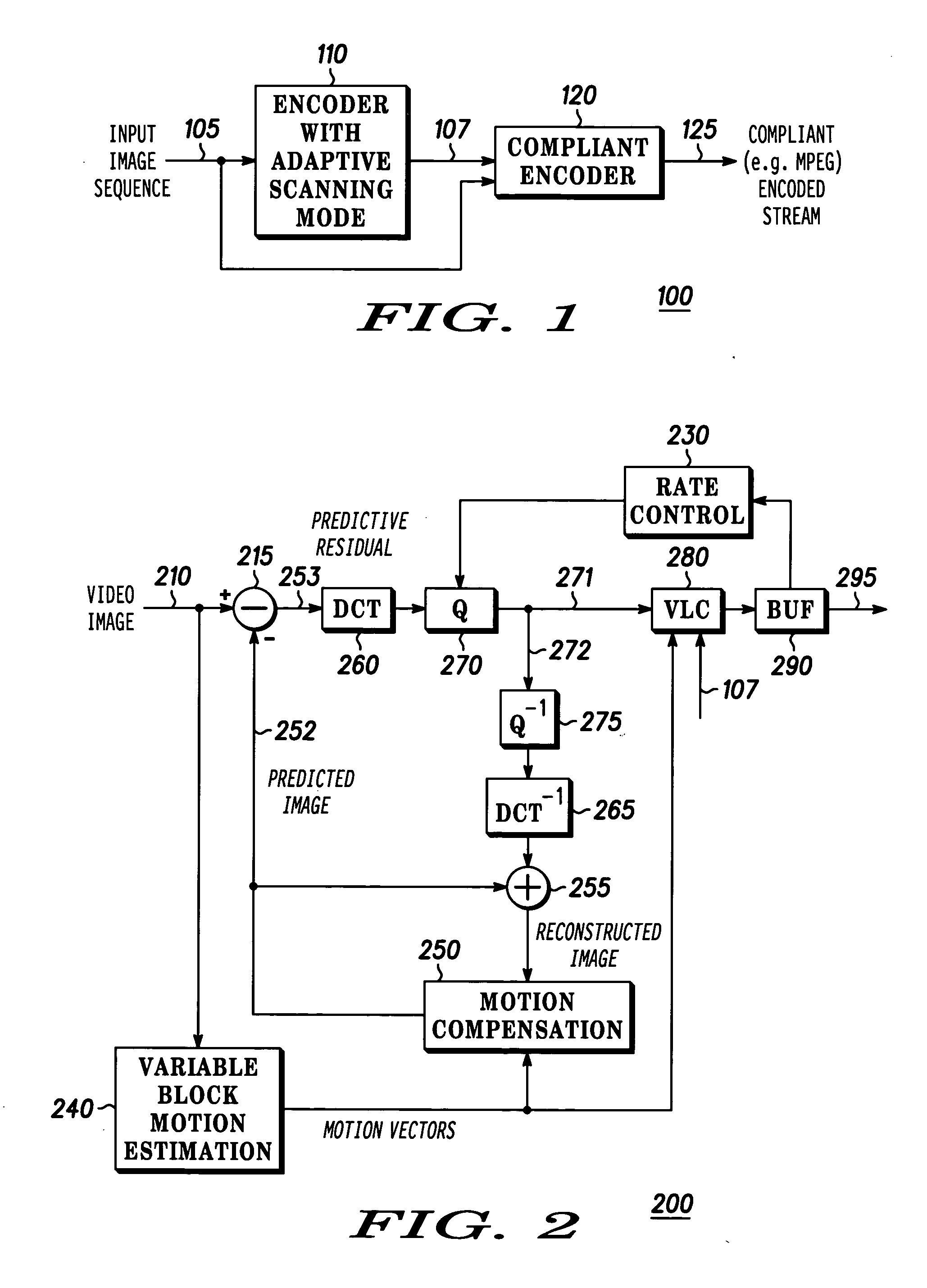
[0020]FIG. 1 illustrates a dual pass encoding system 100 of the present invention. The dual pass encoding system 100 comprises a first encoder 110 and a second encoder 120. In operation, the first encoder 110 implements adaptive scanning mode encoding where each picture within the input image sequence on path 105 is encoding using at least two scanning modes. The resulting encoding efficiency information (e.g., the number of encoding bits used for each scanning mode) for each frame based on the at least two scanning modes is then provided to the second encoder 120. In turn, the second encoder 120 is now provided with the information to allow it to select the proper scanning mode to actually encode the input image sequence 105 into a compliant (e.g., MPEG-compliant) encoded stream on path 125.

[0021] It should be noted that the first encoder 110 need not be a compliant encoder, e.g., an MPEG encoder. The reason is that the image sequence is actually not being encoded into the final c...


PUM


Abstract

The present invention discloses a system and method for adaptive selection of scanning modes based on the content of the input image sequence. In one embodiment, two encoders are employed. A first encoder receives the input image sequence and encodes each frame of the image sequence using at least two different scanning modes, e.g., zigzag scanning mode or alternative scanning mode in accordance with the MPEG-2 standard or the like. Specifically, different portions of each frame will be scanned using different scanning modes. This first encoding provides look-ahead information so that a second encoder is able to assign DCT quantized coefficients in a more efficient scanning order, thereby reducing encoding bits and / or improving the picture quality.

Description

BACKGROUND OF THE INVENTION [0001] 1. Field of the Invention [0002] Embodiments of the present invention generally relate to an encoding system. More specifically, the present invention relates to a dual pass encoding system where scanning mode can be adaptively selected. [0003] 2. Description of the Related Art [0004] Demands for lower bit-rates and higher video quality requires efficient use of bandwidth. To achieve these goals, the Moving Picture Experts Group (MPEG) created the Moving Picture Experts Group (MPEG) created the ISO / IEC international Standards 11172 (1991) (generally referred to as MPEG-1 format) and 13818 (1995) (generally referred to as MPEG-2 format), which are incorporated herein in their entirety by reference. One goal of these standards is to establish a standard coding / decoding strategy with sufficient flexibility to accommodate a plurality of different applications and services such as desktop video publishing, video telephone, video conferencing, digital st...

Claims


Application Information

Patent Timeline
IPC IPC(8): G06FH04N7/12H04N7/26
CPCH04N19/159H04N19/176H04N19/172H04N19/15H04N19/194H04N19/61H04N19/146H04N19/174H04N19/129H04N19/112
Inventor HE, YONGWU, SIU-WAI
Owner GENERAL INSTR CORP
Learn More