Buried fiber optic system including a sub-distribution system and related methods

a fiber optic system and sub-distribution system technology, applied in the field of fiber optic communications systems, can solve the problems of high labor cost and material cost of the drop location, exposed components to the risk of accidental damage, and main distribution cable exposure, and achieve the effects of low installation cost, reduced exposure of distribution cable, and low cos

Inactive Publication Date: 2005-02-17
COMMSCOPE INC
View PDF10 Cites 142 Cited by
  • Summary
  • Abstract
  • Description
  • Claims
  • Application Information

AI Technical Summary

Benefits of technology

[0007] In view of the foregoing background, it is therefore an object of the present invention to provide a fiber optic communication system having a relatively low installation cost, a relatively low cost to add additional subscribers, and that reduces exposure of the distribution cable to damage.

Problems solved by technology

Unfortunately, one drawback of a conventional FITL system is that the main distribution cable must be entered, the fibers accessed, spliced / interconnected and stored within a splice enclosure, and the entire assembly protected at each drop location along the route.
This results in relatively high labor costs and material costs for the drop locations.
This exposes the components to the risk of accidental damage.
Unfortunately, each tap is connected to the secondary cable at a conventional splice enclosure.

Method used


Image

  • Buried fiber optic system including a sub-distribution system and related methods
  • Buried fiber optic system including a sub-distribution system and related methods
  • Buried fiber optic system including a sub-distribution system and related methods

Examples


Embodiment Construction

[0024] The present invention will now be described more fully hereinafter with reference to the accompanying drawings, in which preferred embodiments of the invention are shown. This invention may, however, be embodied in many different forms and should not be construed as limited to the embodiments set forth herein. Rather, these embodiments are provided so that this disclosure will be thorough and complete, and will fully convey the scope of the invention to those skilled in the art. Like numbers refer to like elements throughout, and prime notation is used to indicate similar elements in alternate embodiments.

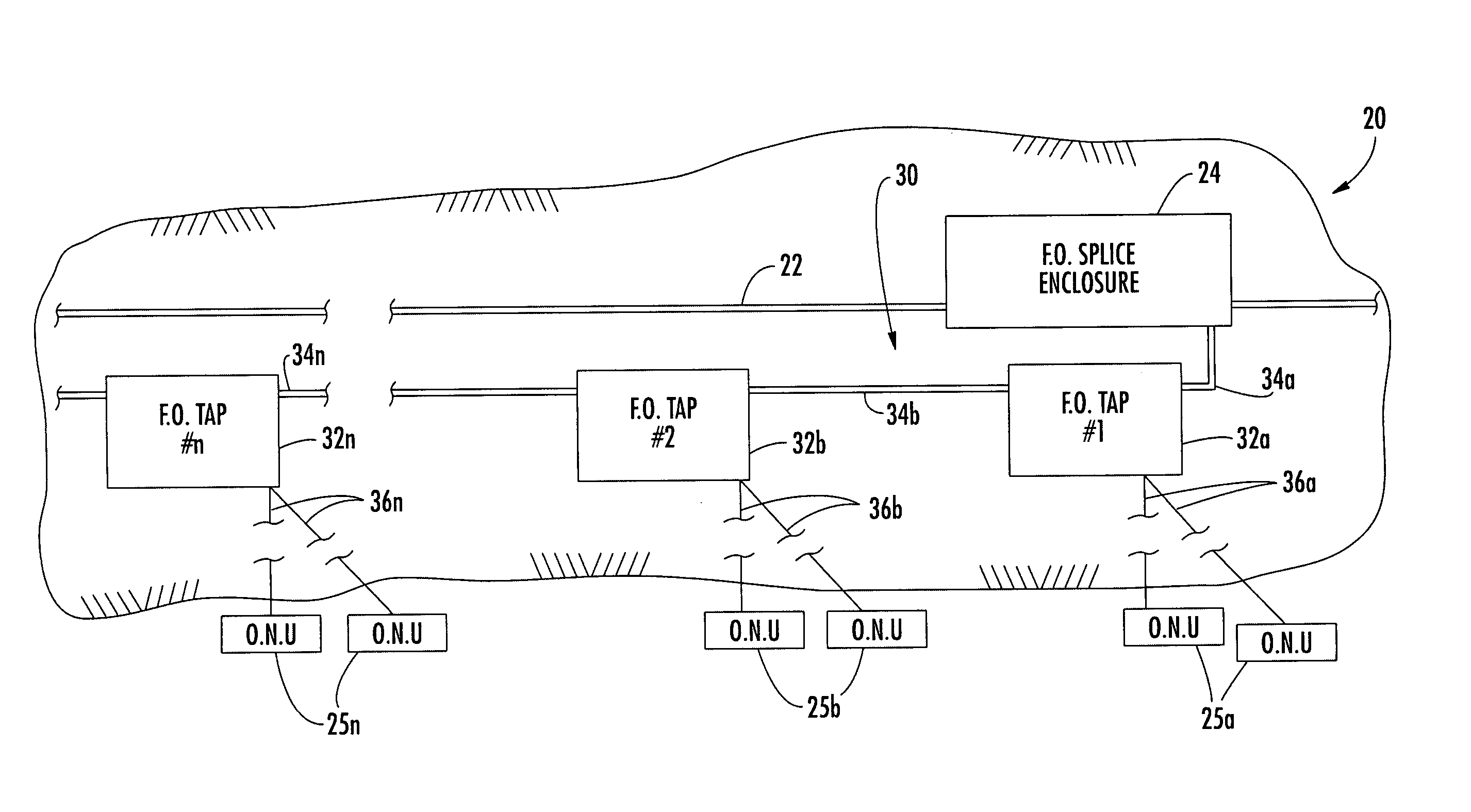
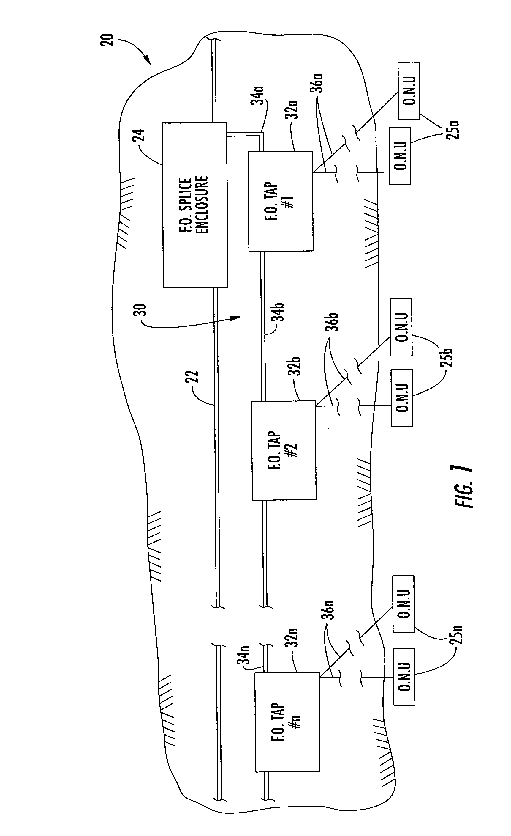
[0025] Referring to FIGS. 1-3, a buried fiber optic cable system 20 is now described. The buried fiber optic cable system 20 illustratively comprises a distribution fiber optic cable 22 extending along a buried route. A fiber optic splice enclosure 24 is illustratively connected to the distribution fiber optic cable 22 along the buried route.

[0026] The buried fiber optic c...


PUM


Abstract

A buried fiber optic cable system includes a distribution cable extending along a buried route, a splice enclosure connected to the distribution cable along the buried route, and a first sub-distribution fiber optic system extending along the buried route in a first direction away from the fiber optic splice enclosure. The first sub-distribution system may include spaced apart fiber optic taps along the buried route, a first sub-distribution fiber optic cable between the fiber optic splice enclosure and a first fiber optic tap, and at least one second sub-distribution fiber optic cable between adjacent fiber optic taps so that the first sub-distribution fiber optic cable and the at least one second sub-distribution fiber optic cable are arranged in end-to-end relation. The system may also or alternately include a similar lateral sub-distribution system.

Description

FIELD OF THE INVENTION [0001] The present invention relates to the field of communications systems, and, more particularly, to the field of fiber optic communications systems, such as installed along buried routes, for example, and associated methods. BACKGROUND OF THE INVENTION [0002] Some cable television systems in the past have used exclusively electrical coaxial cables to distribute TV signals from a headend to a plurality of individual subscribers. A main distribution coaxial cable extended along a route, and a series of taps were connected to the main distribution cable along the route. One or more coaxial drop cables extended outwardly from the taps to the individual subscribers. [0003] Fiber optic cables are widely used for transmitting telecommunications signals over relatively long distances, and at higher data rates than electrical cables, such as coaxial cables. Fiber optic cables also offer immunity to lightning and other potential electrical faults along the route. A ...

Claims


Application Information

Patent Timeline
Patent Type & Authority Applications(United States)
IPC IPC(8): H04B10/272G02B6/00G02B6/44G02B6/50
CPCG02B6/4451H04B10/272G02B6/504G02B6/501
Inventor VOGEL, MARK O.GEMME, CHRISTOPHER P.ALRUTZ, MARK E.LEE, MARTIN B.
Owner COMMSCOPE INC
Why Eureka
Try Eureka