Thermal printer and cutter

Inactive Publication Date: 2005-02-17
FUJITSU COMPONENENT LTD
View PDF7 Cites 36 Cited by
  • Summary
  • Abstract
  • Description
  • Claims
  • Application Information

AI Technical Summary

Benefits of technology

[0016] A first more specific object of the present invention is to provide a thermal printer that can realize miniaturization and weight saving thereof.
[0017] A second more specific object of the present invention is to provide a cutter that can res

Problems solved by technology

Accordingly, it is difficult to realize a small-sized thermal printer because the thermal printer includes both the thermal printer body and the cutter device.
This difficulty also incurs difficult miniaturization of a POS terminal and a ticket vending machine.
However, such a

Method used


Image

  • Thermal printer and cutter
  • Thermal printer and cutter
  • Thermal printer and cutter

Examples


first embodiment

[0128] the present invention is described.

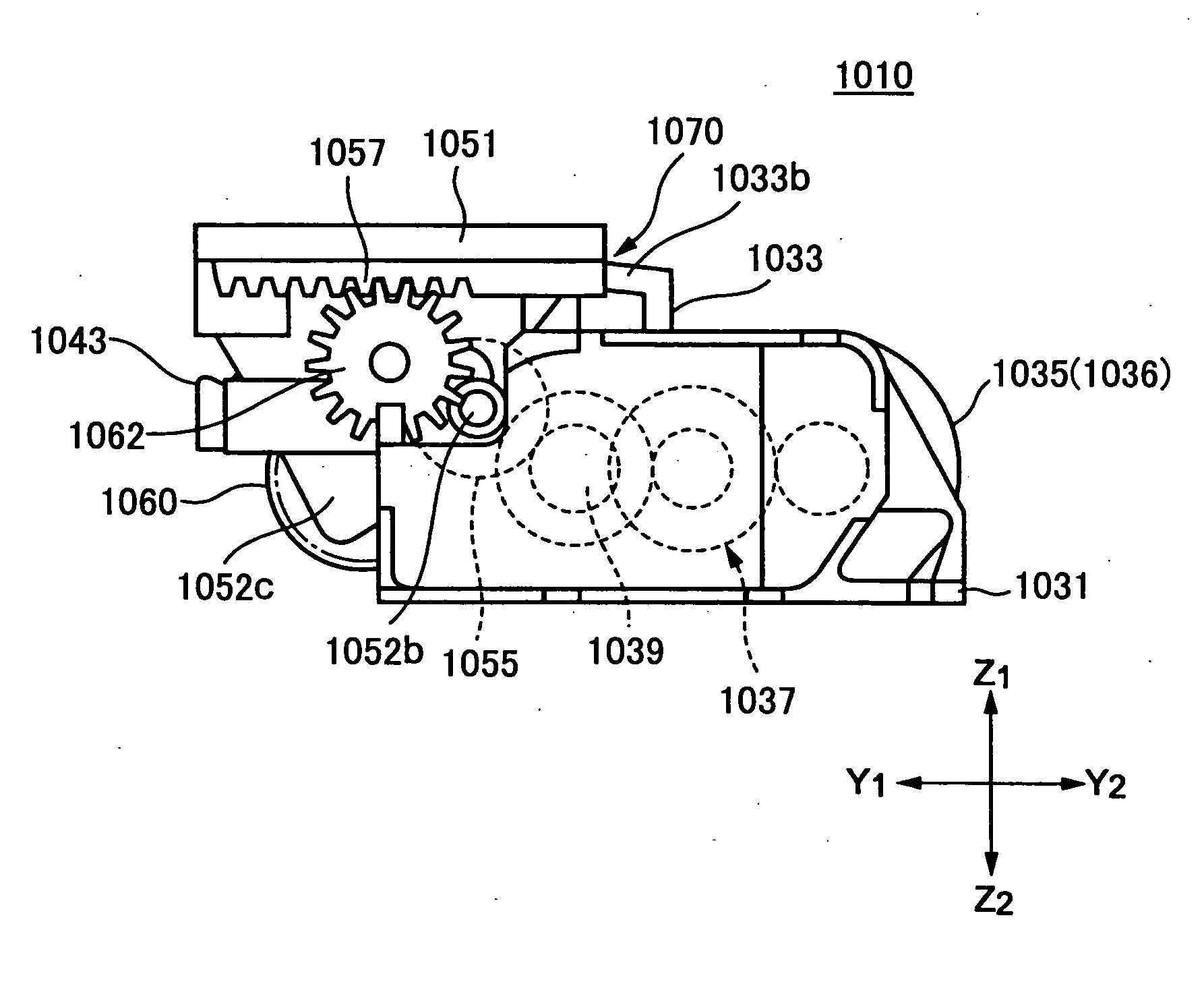
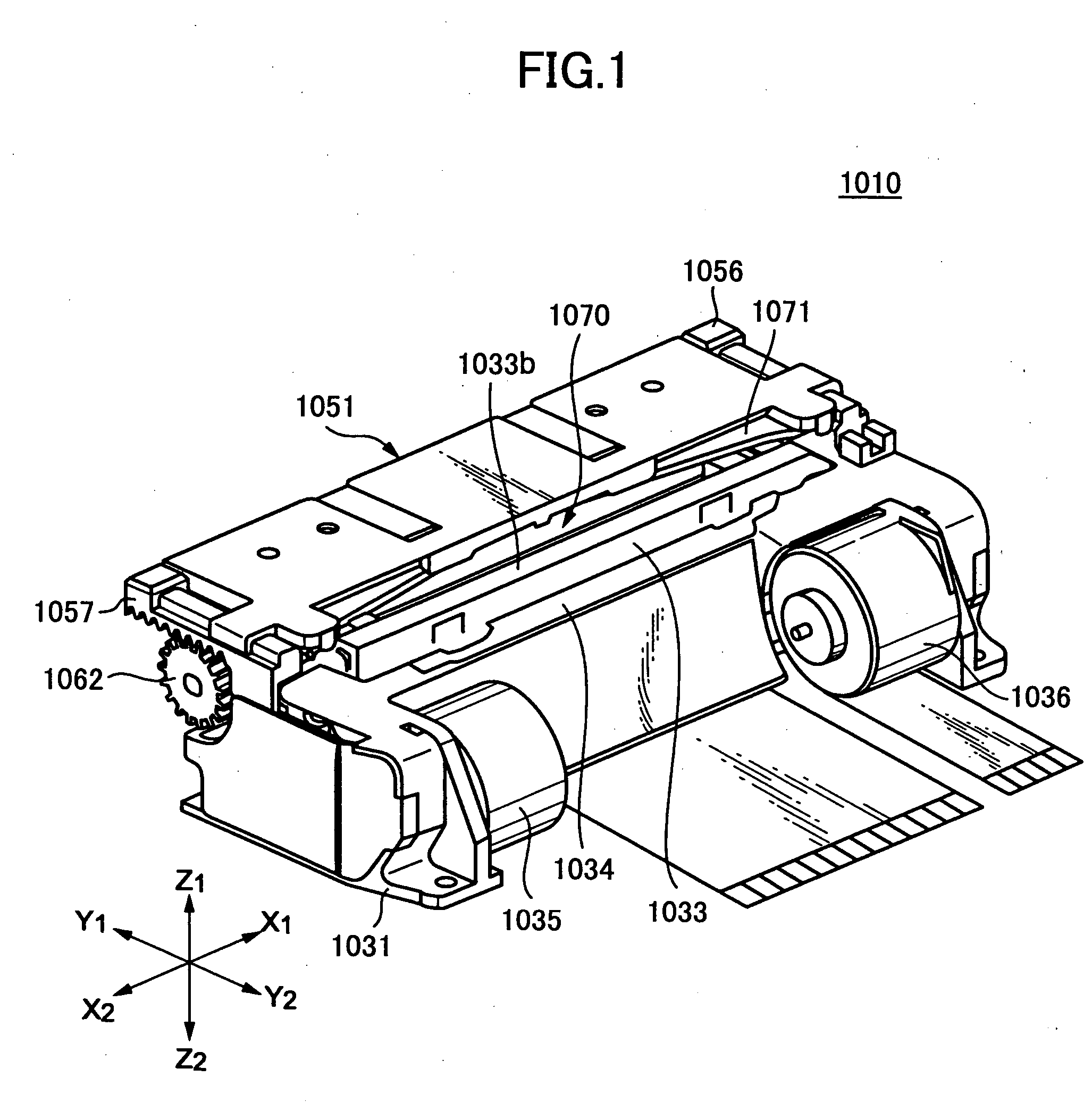
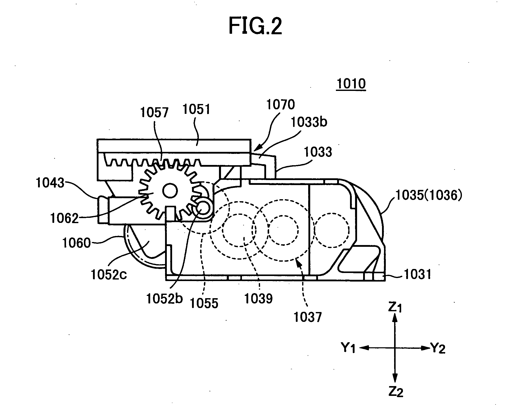
[0129]FIG. 1 and FIG. 2 show a thermal printer 1010 according to the first embodiment of the present invention. FIGS. 3A through 3C are schematic views showing the terminal printer 1010. The thermal printer 1010 is configured as a line printing and clamshell type thermal printer. FIGS. 4A and 4B show a mobile terminal device 1020 incorporating the thermal line printer 1010. FIG. 5 shows an exemplary structure of the mobile terminal device 1020 in a case where the mobile terminal device 1020 includes the thermal line printer 1010. Throughout these drawings, the X1-X2 shaft, the Y1-Y2 shaft and the Z1-Z2 shaft represent the width direction, the length direction and the height direction, respectively.

[0130] [Overall Structure and Operation]

[0131] The thermal printer 1010 has such a structure that a first module 1030 shown in FIG. 6 is detachably combined with a second module 1050 shown in FIG. 7 and a cutter part 1070 is formed in a condition ...

third embodiment

[0312] the present invention is described.

[0313]FIGS. 72A through 72E roughly show exemplary structures of two specific types of thermal printers according to the third embodiment of the present invention. FIGS. 72A and 72B show exemplary structures of a first specific thermal printer 3010-1 and a second specific thermal printer 3010-2. The first specific thermal printer 3010-1 has such a structure that a first specific second module 3050-1 shown in FIG. 72D is detachably coupled with a first module 3030 shown in FIG. 72C. In addition, a cutter part is formed in the connection condition. On the other hand, the second specific thermal printer 3010-2 has such a structure that a second specific second module 3050-2 is detachably coupled with the first module 3030 shown in FIG. 72C. In addition, a cutter part is formed in the connection condition. In the first specification, the print resolution with respect to a paper feed direction is set as 203 dpi (dots per inch), and on the other h...


PUM

PropertyMeasurementUnit
Widthaaaaaaaaaa

Abstract

A thermal printer includes a first module having a motor and a thermal head support member to fix a thermal head, the thermal head support member having a fixed blade part working as a blade and an a second module being detachably coupled with the first module, the second module having a platen roller, a movable blade member and a movable blade member movement mechanism to move the movable blade member, wherein the movable blade member is disposed to face the fixed blade part and driving force of the motor is conveyed to the movable blade member movement mechanism, and thereby a cutter part is formed.

Description

BACKGROUND OF THE INVENTION [0001] 1. Field of the Invention [0002] The present invention relates to a thermal printer and a cutter. More particularly, the present invention relates to a thermal printer and a cutter that can cut a paper in such a way that a printed portion of the paper can be partially cut to leave a plurality connection points. [0003] 2. Description of the Related Art [0004] A thermal printer device having a function to automatically cut a roll paper is often incorporated in a POS (Point Of Sale) terminal and a ticket vending machine. [0005] For example, as disclosed in Japanese Laid-Open Patent Application No. 2000-094767, a conventional automatically paper cutting type of thermal printer has a structure such that a cutter device, which is configured as an individual unit, is mounted to a thermal printer body including a thermal head, a platen and a motor. Such a cutter device includes a fixed blade, a movable blade and a motor to move the movable blade. [0006] Ac...

Claims


Application Information

Patent Timeline
IPC IPC(8): B26D1/00B26D1/08B26D5/08B26D7/26B26F1/18B41J11/66B41J11/70B41J15/04
CPCB26F1/18B41J11/663B41J11/666B41J11/70B41J15/042B26D2007/2685B26D1/085B26D5/08B26D7/2628B26D2001/006B26D1/0006Y10T83/8822Y10T83/8749
Inventor WATANABE, SUMIOMORI, YUKIHIROTSUCHIYA, MASAHIRO
Owner FUJITSU COMPONENENT LTD
Why Eureka
Try Eureka