Tracked compact utility loader

a compact, track-mounted technology, applied in mechanical machines/dredgers, soil-shifting machines/dredgers, transportation and packaging, etc., can solve the problems of various damage and/or operational difficulties, debris often gets wedged between the front track support member, and rocks,

Inactive Publication Date: 2005-02-17
TORO CO THE
View PDF19 Cites 30 Cited by
  • Summary
  • Abstract
  • Description
  • Claims
  • Application Information

AI Technical Summary

Problems solved by technology

However, in such environments, the Applicants have found that rocks, pieces of dirt, and miscellaneous other pieces of debris often get caught between the tracks and the rotatable track support members.
For example, when operating a tracked loader in an outdoor environment in which dirt is being moved, such as when an area of ground is being graded, this debris often gets wedged between the front track support member and the track.
When debris gets wedged between the track and the track support members, various damage and / or operational difficulties often occur.
For example, the debris can cause the track to jam which, in turn, can cause the track or other components of the traction system to break.
In addition, the track can also become detracked, namely to be pushed off one or both of the track support members, thereby disabling the traction system and the loader.
Obviously, these disadvantages detract from the use of a tracked loader in outdoor environments that contain various pieces of debris.
Another problem with the Rohrbaugh loader is the use of an extensible and retractable boom to mount the ground engaging attachment.
This boom is so large and is so positioned on the loader that it substantially obstructs the view of the operator if the operator is attempting to work the ground immediately in advance of the loader.
The operator simply cannot see what he is doing with the attachment when using the Rohrbaugh loader.
Moreover, using a rotatable turntable to mount the boom further complicates the structure and provides a loader which, while versatile, has more components and drive systems that are susceptible to breaking down.

Method used


Image

  • Tracked compact utility loader
  • Tracked compact utility loader
  • Tracked compact utility loader

Examples


Embodiment Construction

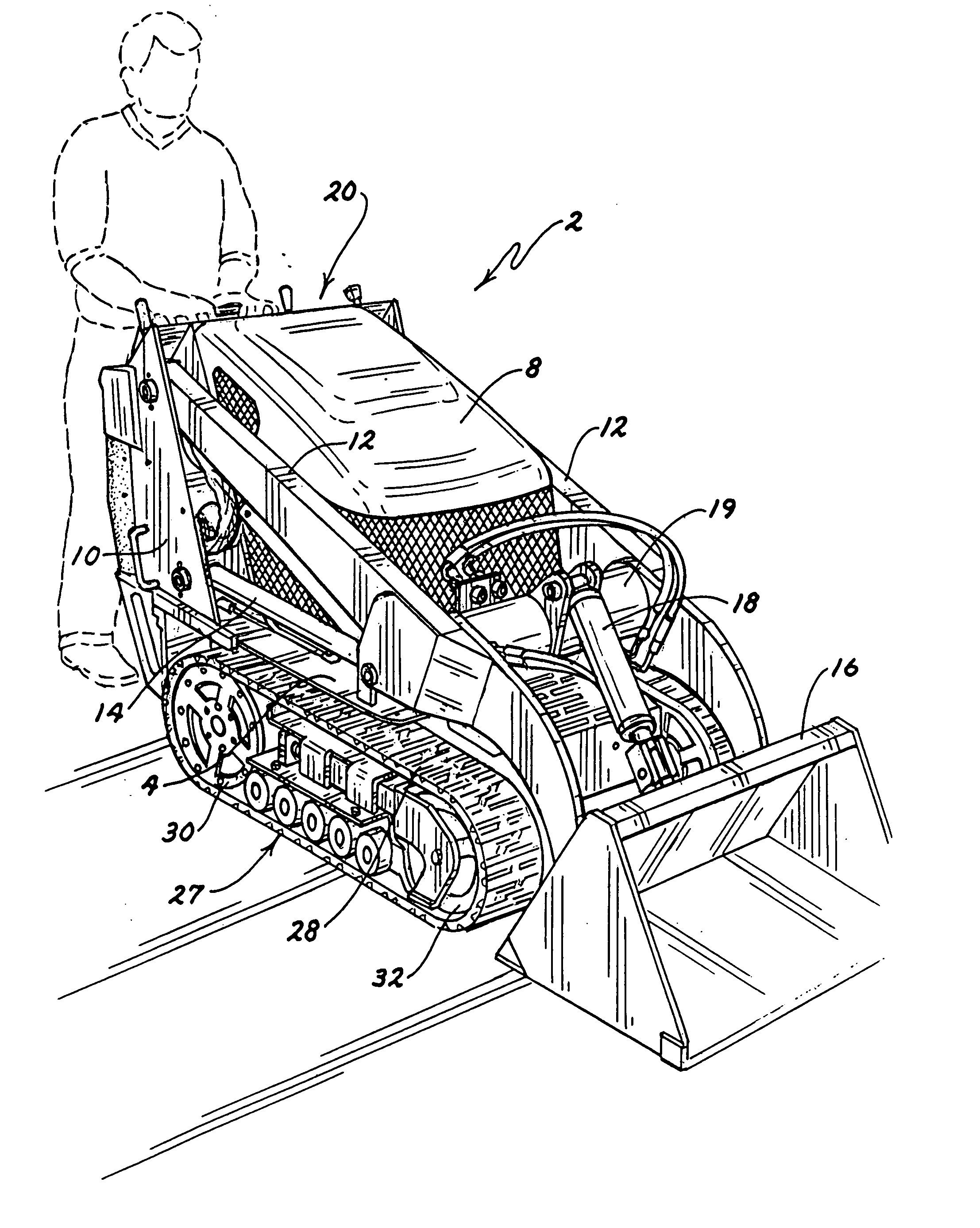
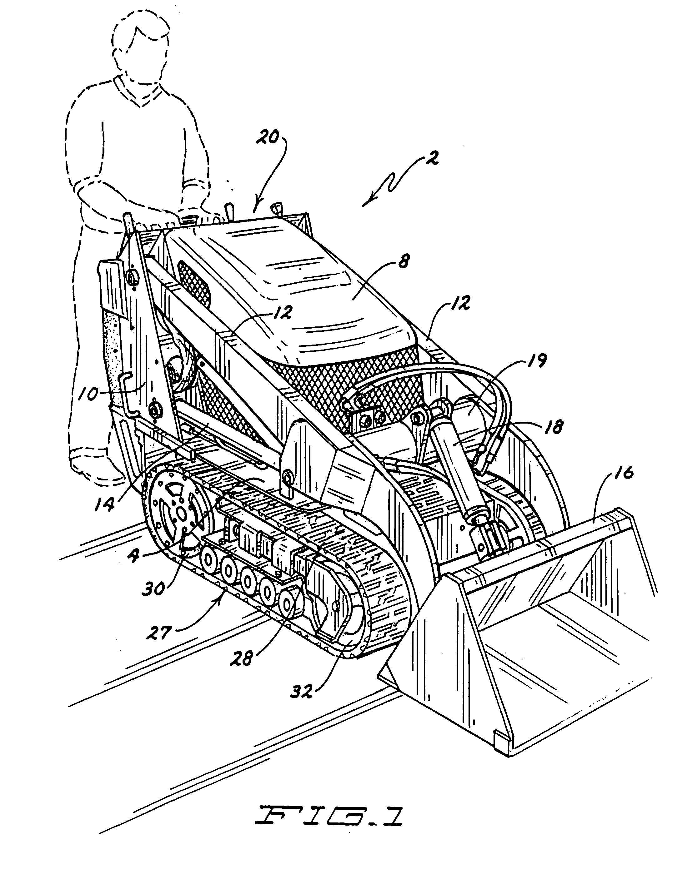
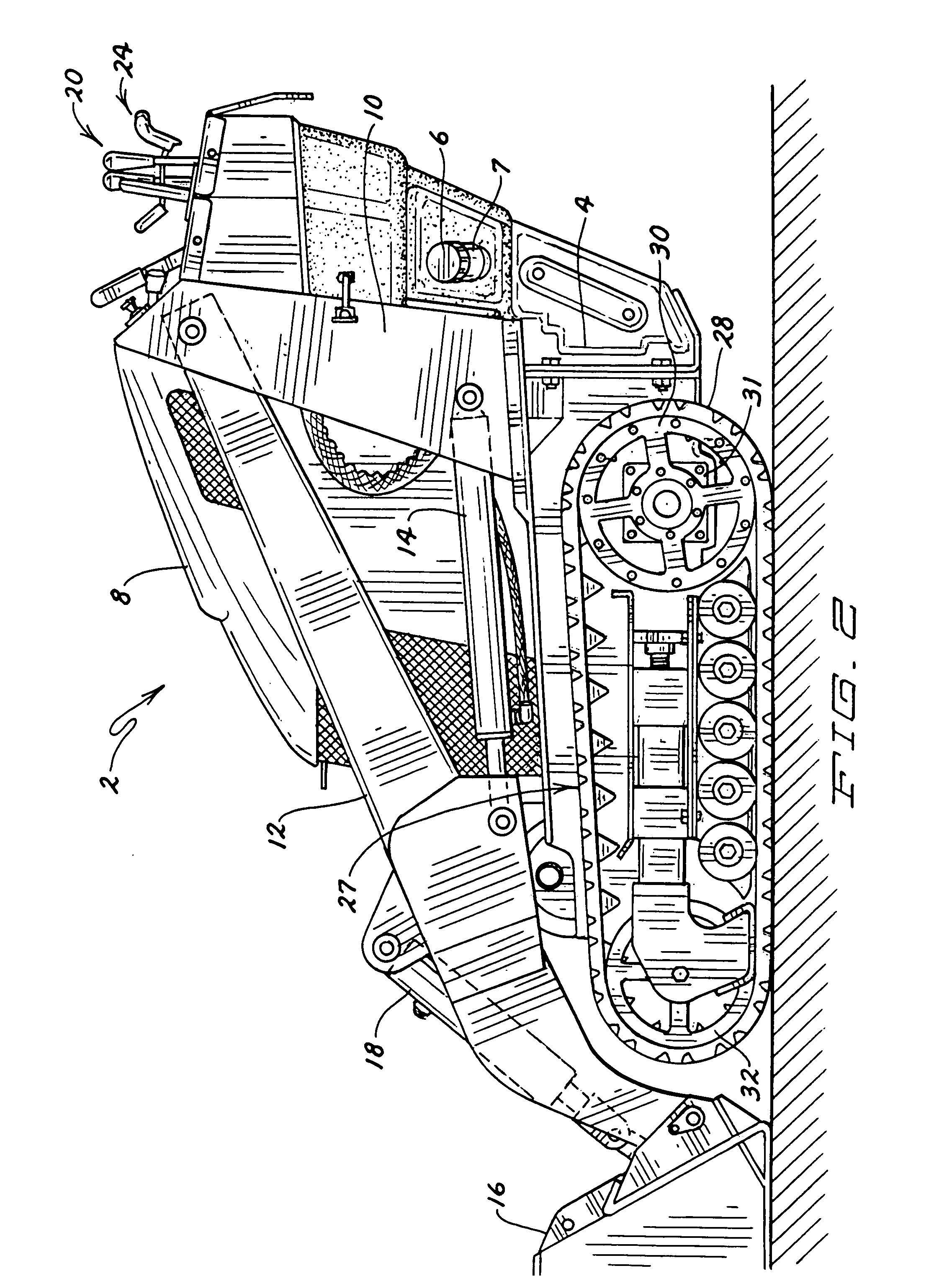
[0032] This invention relates to an outdoor equipment unit for performing ground grooming or ground working operations. More particularly, one embodiment of this invention relates to an outdoor equipment unit comprising a compact utility loader 2. Loader 2 of this invention has a tracked traction system for propelling loader 2 over the ground.

[0033] Loader 2 can be used by landscape contractors to perform various ground working operations when constructing or creating a desired landscape. For example, a bucket can be attached to loader 2 for scooping and carrying dirt, a ground leveling plane can be attached to loader 2 for blading and leveling the ground surface, a trencher can be attached to loader 2 for cutting a trench in the ground, etc. In addition, loader 2 can perform various ground grooming operations. For example, loader 2 can be used by maintenance personnel to remove snow when a snow plowing blade is attached thereto.

[0034] Referring first to FIGS. 1-4, loader 2 includ...


PUM


Abstract

This invention relates to an outdoor equipment unit such as a walk-behind skid steer loader. The loader has a tracked traction system in which endless tracks are entrained around a rear drive support member and a front support member. The front support member is spring biased forwardly, but can move rearwardly against the spring bias to allow debris that is caught between the front support member to clear itself to help prevent the track from untracking. A single control handle having front and rear hand grips located between a fixed grab bar can be rotated and / or twisted to control the traction system. Return to neutral systems ensure that the control handle will return to a centered, neutral position upon release of the control handle by the operator.

Description

CROSS-REFERENCE TO RELATED APPLICATION [0001] This application is a continuation-in-part of Ser. No. 10 / 254,047, now U.S. Pat. No. 6,709,223.TECHNICAL FIELD [0002] This invention relates to a compact utility loader which has a traction system and is guided by an operator who walks behind the loader. More particularly, this invention relates to a tracked traction system particularly adapted for use in outdoor, relatively hostile, debris laden environments. BACKGROUND OF THE INVENTION [0003] U.S. Pat. No. 5,423,654 to Rohrbaugh discloses a tracked, walk-behind loader for use in the coal mining industry. The loader includes a rotary turntable which mounts an extensible boom. An attachment, such as a bucket, is pivotally mounted on the front of the boom. The boom can be swung about a vertical axis by virtue of the turntable. In addition, the boom can be pivoted about a horizontal axis to vary its angle of inclination relative to the ground, the boom can be telescoped and retracted to va...

Claims


Application Information

Patent Timeline
Patent Type & Authority Applications(United States)
IPC IPC(8): B62D51/04B62D55/00E02F3/34E02F9/02E02F9/08E02F9/20
CPCB62D51/04B62D55/00E02F9/2004E02F9/02E02F9/0808E02F3/3414
Inventor WALTO, JOSEPH J.STALPES, PHILIP G.
Owner TORO CO THE
Why Eureka
Try Eureka