Rotary vane pump seal

a technology of rotary vane pump and seal, which is applied in the direction of rotary/oscillating piston pump components, machines/engines, liquid fuel engines, etc., can solve the problems of less efficiency than the basic embodiment, and achieve the effect of improving the efficiency of existing vane pump and motor, facilitating digital control, and extending the service li

Inactive Publication Date: 2005-02-17
KASMER THOMAS E
View PDF80 Cites 8 Cited by
  • Summary
  • Abstract
  • Description
  • Claims
  • Application Information

AI Technical Summary

Benefits of technology

[0008] Reshaping of the flexible band is necessary to control the swept chamber volume of the pump as the rotor is turning and comprises an array of radially movable pistons which are at 0.degree., 90.degree., 180.degree, and 270.degree. around a full circle, i.e. at 12 o'clock, 3 o'clock, 6 o'clock, and also 9 o'clock of a clock face. Each of the pistons has an appropriate curvature to contact the flexible band external surface in the positions cited. If the 12 o'clock and 6 o'clock pistons are caused to move inward, the fixed circumference of the flexible band causes the 3 o'clock and 9 o'clock pistons to move outward by an equal amount. The inward or outward movement of the pistons may be driven by individual controlled hydraulic pressures, or the movement can be caused by mechanical means such as a gear and rack, or radially disposed screw drives to each piston. Another type of piston control means would be the joining of an analog type electric servo motor drive to a ball screw mechanism with an encoder position feedback; which arrangement would easily lend itself to digital control. Whatever the method of controlling the movement of the piston, the final purpose is to controllably elliptasize the flexible band from an axial perspective so as to cause the controlled and varying degrees of swept volume of fluid flow per revolution of the vane pump or motor. In the basic embodiment of this invention, opposing pairs of pistons move simultaneously toward or away from each other, while the remaining set of opposed pistons behave in simultaneous opposition to the action of the first pair. This behavior results in varying degrees of elliptic reshaping of the flexible band viewed from the axial perspective of the vane rotor. A novel and significant aspect of this device is the freedom of movement of the flexible band, which is impossible in the prior art. This includes special manipulation of the pistons and band that allow the combination of this invention to simultaneously manipulate two common fluid, but hydraulically separate, outputs of this device as pump or motor. The variable pressure balanced design has two equal and identical pressure fluid outputs which will be merged so as to drive a hydraulic motor to form what is called a hydrostatic transmission. This is a second embodiment of the present invention. In addition, a second variable vane device of the proposed design may act as a motor in a conventional type of hydrostatic transmission with all of the current results, but with much greater efficiency and range. Another embodiment of the invention is a special piston manipulation which causes this invention to act like the earlier variable non-pressure balanced construction pumps with a single input and output. In the present invention, there is shown two separate hydraulic circuits with separate inputs and outputs where a single pump of the proposed design is separately connected to two fixed displacement hydraulic motors. Motor Number 1 will connect in closed hydrostatic loop with the first and second quadrant ports of the pump, while motor Number 2 will connect in closed hydrostatic loop...

Problems solved by technology

The well known limitation of the prior art; namely the sliding edge friction associated with the combined outward radial force of the vanes is totally eliminated since there is substantially no relative motion between outside edg...

Method used


Image

  • Rotary vane pump seal
  • Rotary vane pump seal
  • Rotary vane pump seal

Examples


Embodiment Construction

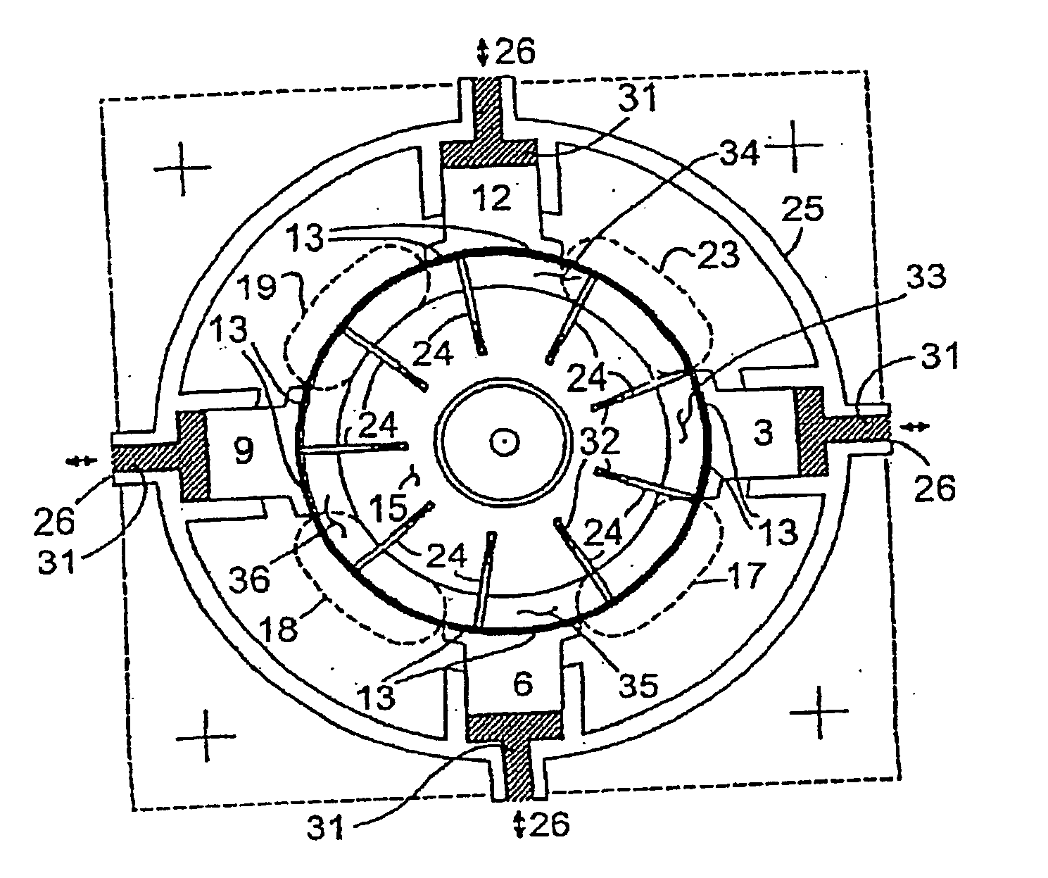
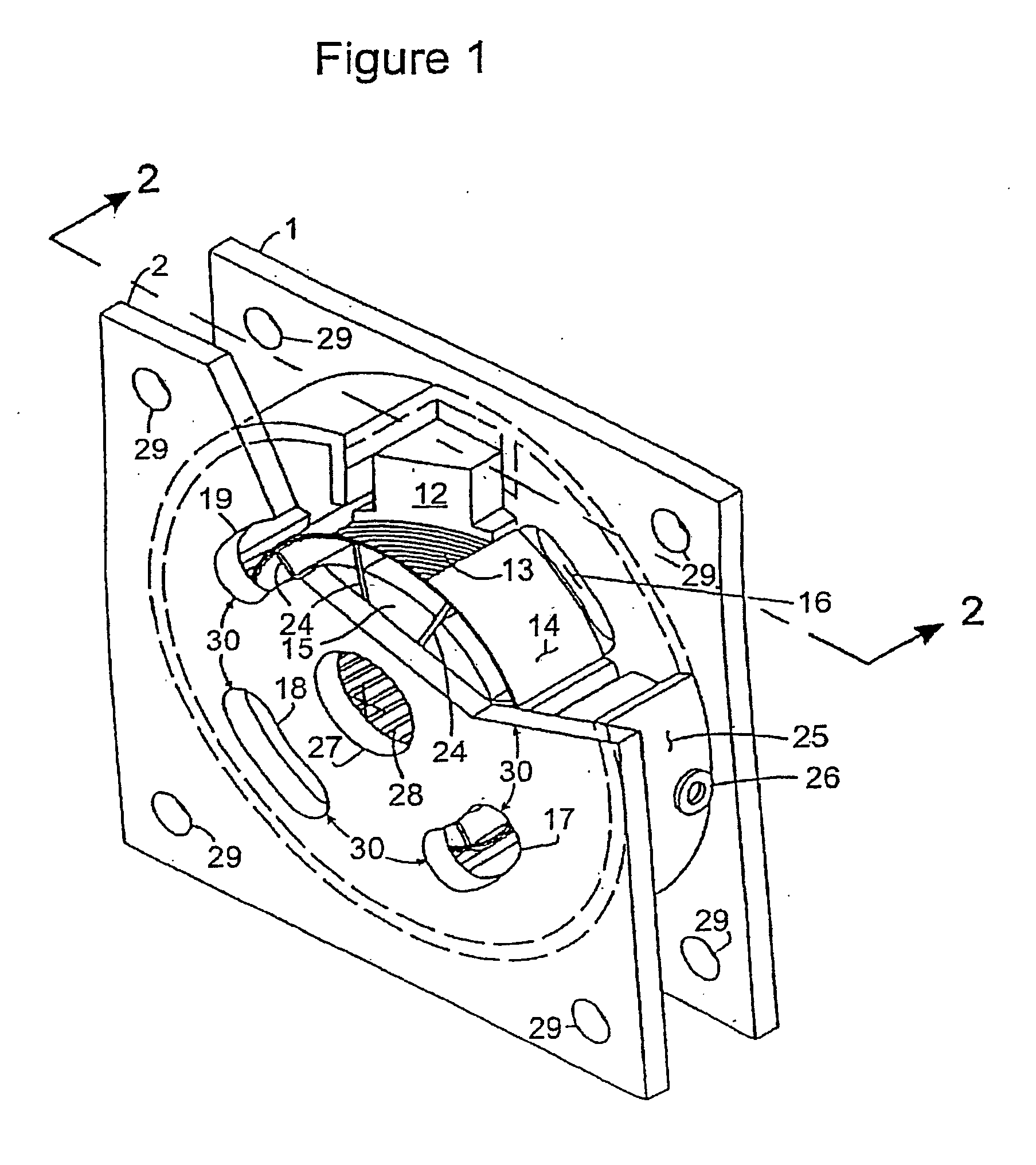
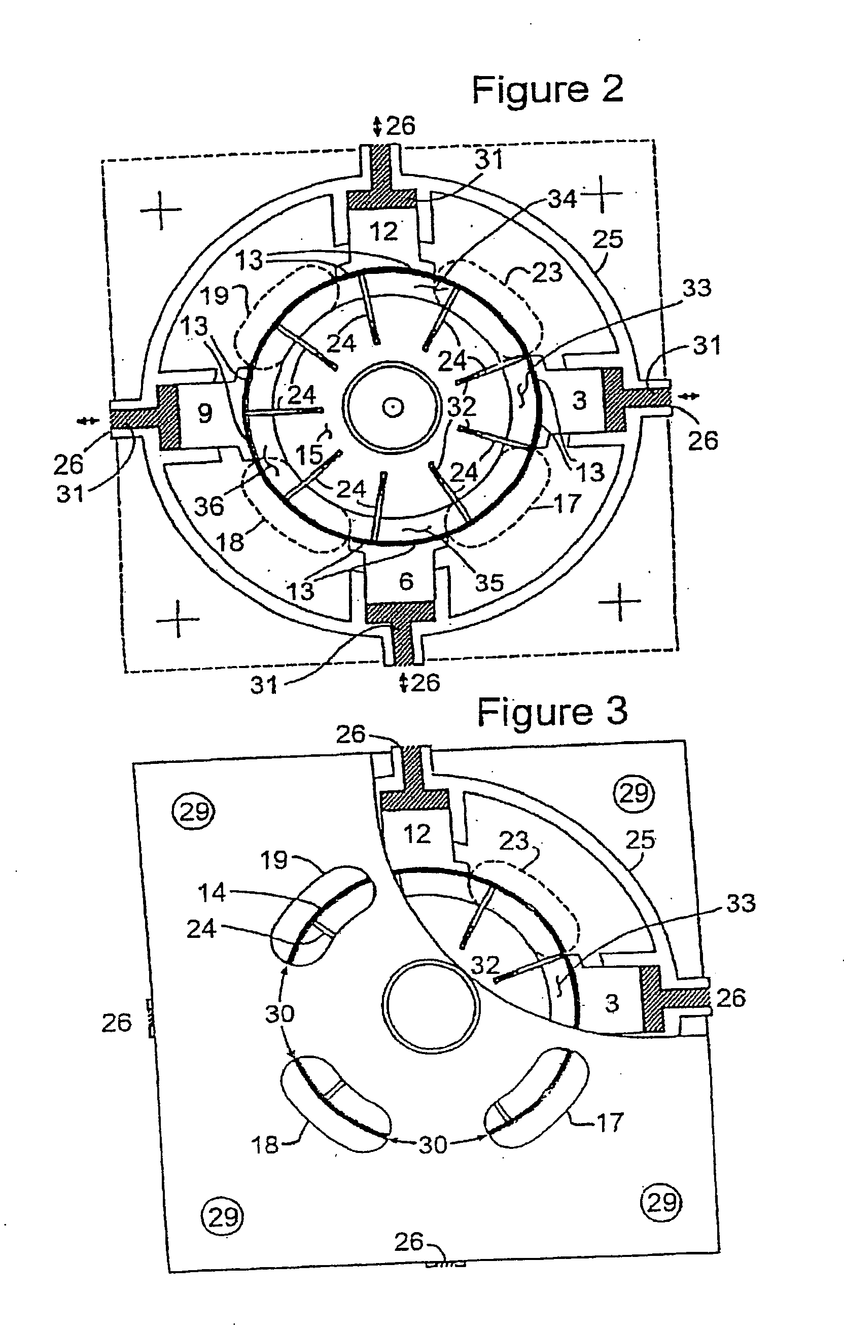
[0020] The isometric view shown in FIG. 1 has a frontal first quadrant cutaway which exposes some very important features of the invention. The rear end plate 1 is shown with the first quadrant kidney port 16 exposed. The front end plate 2 is partially cutaway with the kidney ports 17, 18, and 19 respectively in the second, third, and fourth quadrants showing. The rear end plate 1 has like kidney ports 20, 21, and 22 in axial alignment with ports 17, 18, and 19, but those ports in plate 1 are out of view in this drawing. This view shows like kidney ports front and back. However, it is only necessary to have one port per quadrant chamber to allow for fluid flow into and out of the chamber. Either the front or rear ports can be utilized, or both can be used to increase the flow capacity. Also, referring to FIG. 4, any other means of porting which allows fluid to flow into or out of the volume 33, 34, 35, or 36 when they rotate in alignment with “quadrants one, two, two, three, or four...


PUM


Abstract

A rotary vane pump is provided that provides an improved fluid replenishment and pressure relief system within a rotary vane pump system. A system, containing a rotary vane pump containing at least one relief cut between the housing and the rotor, functions to relieve fluid pressure normally found between the housing and the rotor. The fluid leaks from areas such as the rotational clearance required between the rotor and an inner wall of the housing. The system includes a reservoir in fluid communication with the relief cut wherein fluid leaks are then retained within the reservoir. A fluid distribution manifold employing a plurality of check valves, each corresponding to a respective chamber within the rotor, provides a controlled fluid feed from the reservoir to the rotor thereby balancing the fluidic pressure existing between the radially innermost ends of the vanes and the radially outermost ends of the vanes.

Description

CROSS-REFERENCE TO RELATED APPLICATIONS [0001] This application claims the benefit of U.S. Provisional Application No. 60 / 494,327 filed on Aug. 11, 2003 and herein incorporated by reference in its entirety.TECHNICAL FIELD [0002] This application relates to rotary vane pumps and specifically to improvements in the sealing, fluid replenishment, and pressure relief of systems incorporating rotary vane pumps. Related co-owned U.S. Pat. Nos. 6,022,201, 6,527,525, and 6,612,117 are herein incorporated by reference in their entirety. BACKGROUND OF THE INVENTION [0003] Early devices varying the displacement of vane pumps involved the deliberate offset of the rotational center of the vane rotor with respect to the geometrical center of the circular outer case. The amount of offset would then control the swept volume of the pump and thereby provide a desired volumetric output for each rotation of the rotor. Several problems with this design limited its use. [0004] First, the pressure unbalanc...

Claims


Application Information

Patent Timeline
IPC IPC(8): F01C21/08F04C5/00F04C11/00F04C14/20F04C15/00
CPCF01C21/0863F04C11/003F04C2230/60F04C2230/00F04C14/20
Inventor KASMER, THOMAS E.
Owner KASMER THOMAS E
Why Eureka
Try Eureka