Microchannels for efficient fluid transport

a microchannel and fluid technology, applied in the field of fluid transport and microchannels, can solve the problems of difficult, if not impossible, to draw fluid out of the tube, and difficult, if not impossible, to draw fluid into the tube, so as to reduce the viscosity of the microchannel, enhance fluid transport, and reduce the viscosity. the effect of resistan

Inactive Publication Date: 2005-02-17
RGT UNIV OF CALIFORNIA +1
View PDF7 Cites 19 Cited by
  • Summary
  • Abstract
  • Description
  • Claims
  • Application Information

AI Technical Summary

Benefits of technology

The present invention provides a structure having one or more microchannels, referred to herein as microtubes, capable of dispensing femto-liter volumes of fluid in a controlled fashion. The microtubes can form air gaps between the inner surface of the microtube and a fluid in the microtube. Such air gaps can reduce viscous resistance by a factor of 5 or more. Moreover, the hydrophilic and hydrophobic surface properties of the microtubes can provide enhanced fluid transport by adjusting surface tension. In accordance with this invention, microtubes with textured inner surfaces form air gaps. The microtubes can have inner diameters from about 10 nm up to about 1000 microns.
In accordance with this invention, a structure is provided containing a microchannel, such as in a microtube, capable of forming air gaps between the its inner surface and a fluid in the microchannel, the air gaps reducing the viscous resistance of the microchannel as compared with the viscous resistance of a microchannel of similar dimensions that is incapable of forming air gaps. More particularly, the inner surface of the microchannel is textured with peaks and valleys whereby the hydrophobic and hydrophilic surface properties of the microchannel are sufficient to adjust the surface tension of a fluid so that the fluid can be transported into and out of the microchannel. For example, the peaks can be defined by particles on the surface of the microchannel, by a plurality of rings on the surface of the microchannel, or by a spiral coil attached to the inner wall of the microchannel.

Problems solved by technology

Assuming that the working fluid is a hydrophilic liquid, for example, a water-based liquid, and if the micro tube is purely hydrophilic, then it will be very difficult, if not impossible, to draw fluid out of the tube.
On the other hand, if the microtube is hydrophobic, then, again, it will be very difficult, if not impossible, to draw fluid into the tube.

Method used


Image

  • Microchannels for efficient fluid transport
  • Microchannels for efficient fluid transport
  • Microchannels for efficient fluid transport

Examples


example

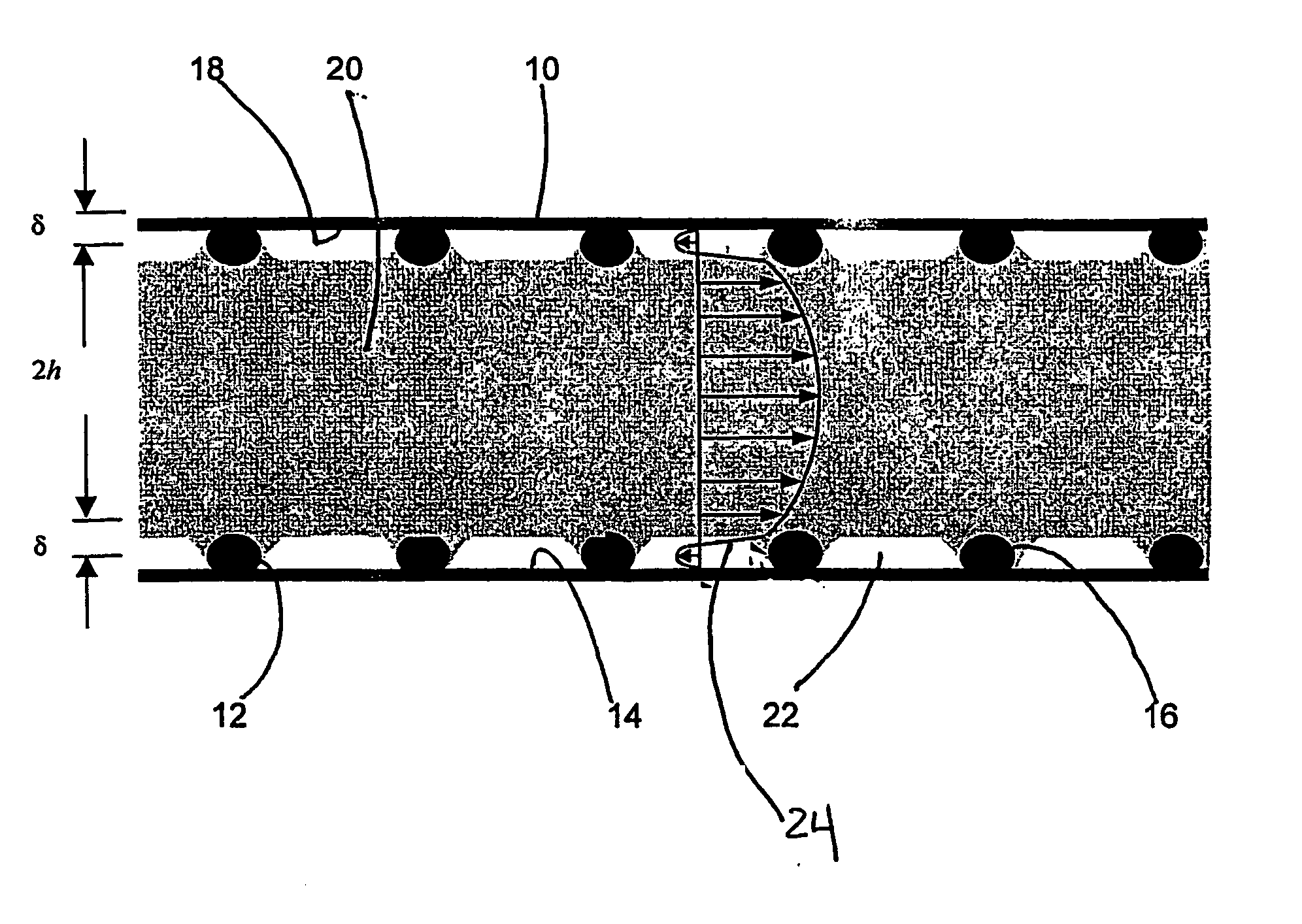
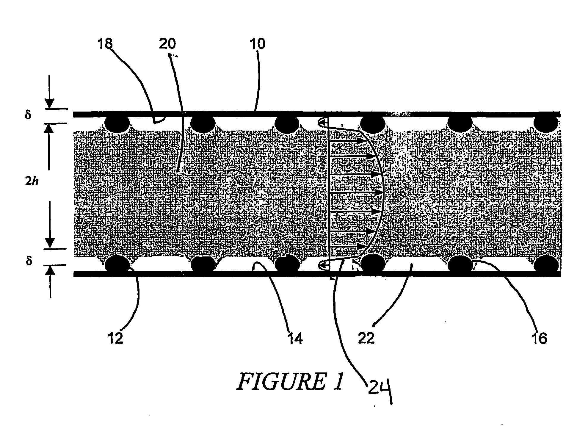
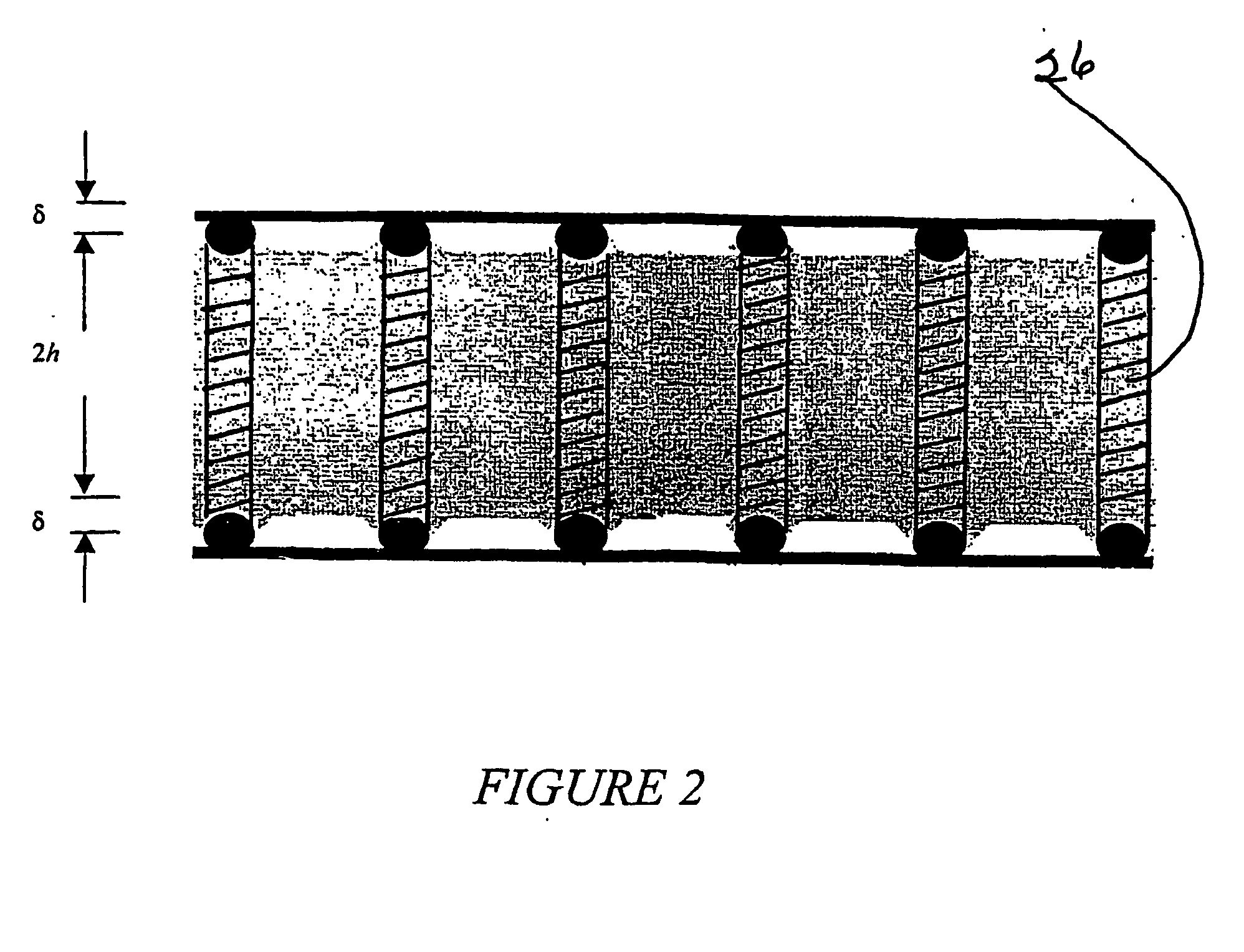
This example, using substrates with flat surfaces, shows how to form a super-hydrophobic surface having hydrophobic peaks and valleys. Basically, polycrystalline alumina substrates were dip-coated in dilute suspensions formed with dispersed, nano-silica particles. The fractional surface coverage of the alumina substrate was varied between ≈0.05 to ≈0.4 by changing concentration of particles in the silica slurry. After a heat treatment to partially sinter the particles to the surface, the surface was made hydrophobic by a reaction with a solution containing fluorosilane molecules.

The ‘as received’ silica slurry (Snowtex-OL, Nissan Chemicals, Tokyo, 20 wt %, particle size 45±5 nm, pH 3±1) was diluted with deionized water to concentrations as low as 0.025 wt %. The pH was adjusted to 6.0±0.2 with tetramethylamonium hydroxide (TMAOH) to produce a well-dispersed slurry. At pH 6, the silica particles were expected to be attractive to the alumina substrates.

Polycrystalline alumina sub...


PUM


Abstract

A structure having one or more micruchannels capable of forming air gaps between the inner surface of the microchannel and a fluid in the microchannel. As a result, the viscous resistance can be decreased by a factor of 5 or more. A microchannel according to this invention can have a textured inner surface which provides for air gap formation. The hydrophobicity of the microchannel can provide enhanced fluid transport by adjusting surface tension.

Description

BACKGROUND OF THE INVENTION 1. Field of the Invention The fields of the invention are fluid transport and microchannels. 2. Background Information The ability to fabricate devices at the micro-and nano-scale has been growing significantly during the past several years. This technology will have a significant impact on society in countless ways during the next decades. One example is in the biotechnology field where delivering minute quantities of highly potent drugs to a single cell is of great interest. This requires devices capable of dispensing on the order of femto-liters (10−15 L) of fluid in a controlled fashion. From a fluid mechanics perspective, the small size scale dictates a large surface to volume ratio. Subsequently, surface tension is a dominating force, and can control the functionality of the microtube for fluid delivery. Assuming that the working fluid is a hydrophilic liquid, for example, a water-based liquid, and if the micro tube is purely hydrophilic, then ...

Claims


Application Information

Patent Timeline
Patent Type & Authority Applications(United States)
IPC IPC(8): B01L3/00B81B1/00
CPCB01L3/5027B01L2400/088B01L2300/166B01L3/502746
Inventor LANGE, FREDERICK F.MEINHART, CARL D
Owner RGT UNIV OF CALIFORNIA
Why Eureka
Try Eureka