
Anastomotic delivery system

a technology of anastomosis and delivery system, which is applied in the field of anastomosis connector and delivery system there, can solve the problems of affecting the anastomosis of the patient, and damage to the connector, so as to reduce the ingress of tissue into the apertur

Inactive Publication Date: 2005-02-17
BY PASS
View PDF0 Cites 33 Cited by
  • Summary
  • Abstract
  • Description
  • Claims
  • Application Information

AI Technical Summary

Benefits of technology

[0022] An aspect of some embodiments of the invention relates to an anastomotic delivery system for delivering an anastomotic connector into a blood vessel and tearing extensions of spikes of the anastomotic connector. In an exemplary embodiment of the invention, the extensions are coupled to a body, to which also a tensioned spring may be coupled. A means for retracting the body, and thus the extensions, is provided. However, when a certain degree of retracting is reached, an interlock locking the spring is released and the spring forcefully retracts the body with a strong force. A potential advantage of this system is that an operator does not apply this force himself and may be less likely to cause inadvertent motion of the delivery system during application of this force. In an exemplary embodiment of the invention, a rotation knob, for example rotated using a thumb, is used to retract the body, for example a tube.
[0026] An aspect of some embodiments of the invention relates to a transfixing assistance device for transfixing a blood vessel on one or more hooks of an anastomotic connector. In an exemplary embodiment, the transfixing device comprises a handle defining a longitudinal axis and an extension offset at an angle to said longitudinal axis. In an exemplary embodiment, when said handle is rotated during said transfixing, the tip of the extension-offset circumducts, for example, according to the curvature of a hook on an anastomotic connector. In an exemplary embodiment, the tip of the extension comprises an orifice (e.g., an aperture or a slot) adapted fit over the hook and to encourage movement of blood vessel tissue in relation to said one or more hooks without damaging the vessel and / or hook during transfixing.
[0030] An aspect of some embodiments of the invention relates to an anastomotic hook guide comprising one or more walls for guiding a plurality of anastomotic hooks into a blood vessel. In an exemplary embodiment, the guide is placed within and / or near an aperture in a blood vessel and guides the anastomotic hooks into the vessel, thereby preventing inadvertent damage to the plurality of hooks from contact with the vessel and / or other biologic tissue in the area.
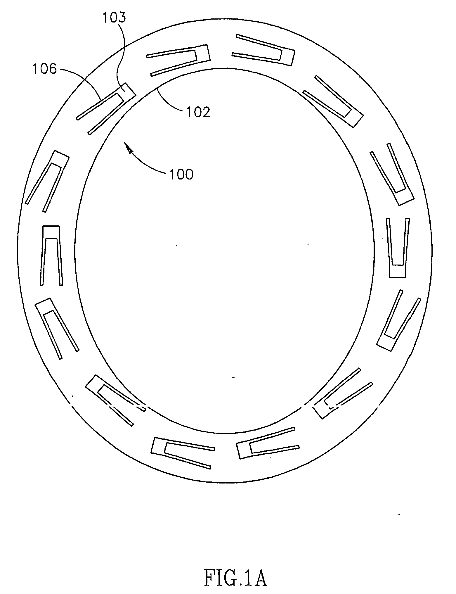
[0034] An aspect of some embodiments of the invention relates to a clip for anastomotic connection including an interlock mechanism. In an exemplary embodiment of the invention, the clip comprises an eye segment and a hook segment, where an interlock mechanism is defined, one part on each segment, to interlocks the two segments, using a single interlock mechanism. In an exemplary embodiment of the invention, the interlocking substantially prevents movement in any direction, possibly providing some elasticity or some freedom of motion due to spaces, however.
[0042] an extension projecting from said handle comprising an orifice at its end, said extension being offset at an angle to said longitudinal axis so that, when said handle is rotated during said transfixing, said tip circumducts at a radius corresponding to its offset angle to said longitudinal axis, said radius suitable for everting a graft over a spiked anastomotic connector. Optionally, said orifice is adapted to transfix blood vessel tissue on said one or more connection hooks without damaging said-tissue.

Problems solved by technology

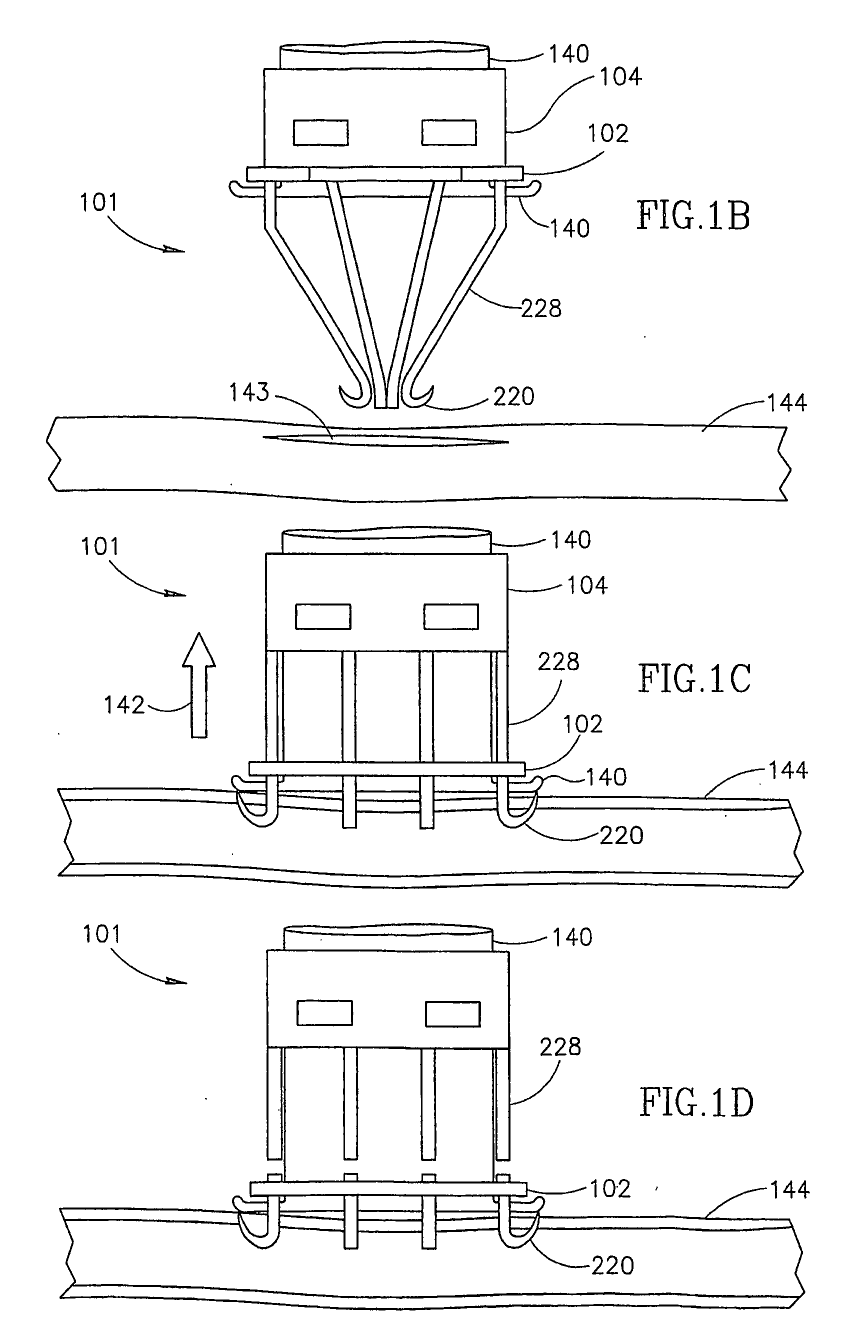
While inadvertent damage of hooks 220 is not a common occurrence, it may result in an improper anastomosis between grafted vessel 140 and host vessel 144, a significant problem in a coronary artery upon which the heart depends for a continuous supply of nutrients, even if no leaking occurs.
Working through the keyhole incision with the slippery, moving and wet structures of the heart and its milieu, can result in damage to connector 101, hooks 220 and / or an improper anastomosis.

Method used


Image

  • Anastomotic delivery system
  • Anastomotic delivery system
  • Anastomotic delivery system

Examples


Embodiment Construction

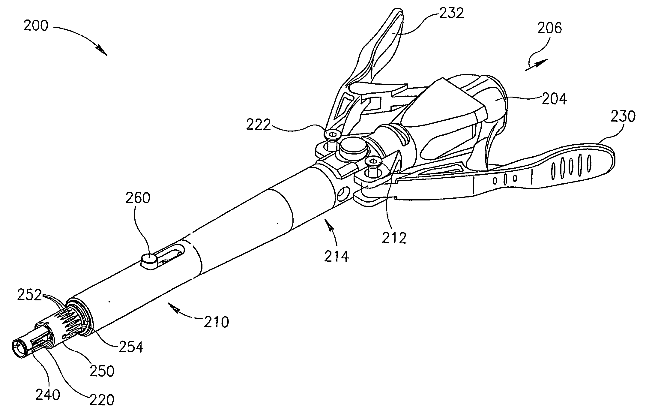
[0139]FIG. 2A is an isometric view of an anastomotic delivery system 200 in accordance with an exemplary embodiment of the invention. System 200 comprises a body 214. A pair of levers 230 and 232 is attached to rotation pins 222 and 212 respectively. Pressing together levers 232 and 230 causes a base 204 to move in a direction 206, as they are pressed toward each other, thereby causing a plurality of hooks 220 of a connector to retract partially into body 214, and then optionally tear off of system 200, for example as described in PCT publication WO 01 / 70090.

[0140] In an exemplary embodiment of the invention, the connector is mounted on a rotation sleeve 250, which allows the connector to be rotated relative to body 214. FIG. 2B is a close-up view of a rotation sleeve 250 of delivery system 200, shown in FIG. 2A, with a protector overtube 240 removed, in accordance with an exemplary embodiment of the invention. Rotation sleeve 250 has been rotated so that hooks 220 are on a horizon...


PUM

PropertyMeasurementUnit
diameteraaaaaaaaaa
diameteraaaaaaaaaa
diameteraaaaaaaaaa

Abstract

An anastomotic connector (200) for attaching two blood vessels comprising a plurality of eye segments (1604), each defining a channel and each including a part of an interlock mechanism (1600) on said channel; a plurality of hook segments (1602), each defining a tissue holding area, each adapted to pass through said channel and including a second part of said interlock mechanism (1600), wherein, said interlock mechanism (1600) engages for a hook and an eye segment when said hook segment (1602) is retracted back into said eye segment (1604) enough to attach two layers of vascular tissue between said eye segment (1604) and said hook segment (1602).

Description

RELATED APPLICATIONS [0001] The present application is a continuation in part of PCT application PCT / IL01 / 00903, filed on Sep. 25, 2001, which designates the U.S., now published in English as WO 02 / 30172, the disclosure of which is incorporated herein by reference. This application is also a continuation-in-part of PCT / IL02 / 00215 filed on Mar. 18, 2002, PCT / IL01 / 01019, filed on Nov. 4, 2001, PCT / IL01 / 00903, filed on Sep. 25, 2001, PCT / IL01 / 00600, filed on Jun. 28, 2001, PCT / IL01 / 00267, filed on Mar. 20, 2001, PCT / IL01 / 00266, filed on Mar. 20, 2001, PCT / IL01 / 00074, filed on Jan. 25, 2001, PCT / IL01 / 00069, filed on Jan. 24, 2001, PCT / IL00 / 00611, filed on Sep. 28, 2000, PCT / IL00 / 00609, filed on Sep. 28, 2000, PCT / IB00 / 00310, filed on Mar. 20, 2000, PCT / IB00 / 00302, filed on Mar. 20, 2000, PCT / IL99 / 00674, filed on Dec. 9, 1999, PCT / IL99 / 00670 filed on Dec. 8, 1999, PCT / IL99 / 00285, filed on May 30, 1999, and PCT / IL99 / 00284, filed on May 30, 1999. The disclosure of all of these applications...

Claims


Application Information

Patent Timeline
Patent Type & Authority Applications(United States)
IPC IPC(8): A61B17/08C12Q1/68
CPCA61B17/11A61B2017/00477A61B2017/0641A61B2017/2923A61B2017/1125A61B2017/1135A61B2017/1107
Inventor LOSHAKOVE, AMIRKILEMNIK, IDOHEFER, GILFRIEDMAN, AHARON SHLOMONATIV, OFER
Owner BY PASS
Learn More