Low-rate battery design

a low-rate battery and low-rate technology, applied in the field of new and improved electrochemical cell construction, can solve the problems of unsatisfactory radial expansion of the cathode and inoptimally designed constructions to provide maximum energy density, and achieve the effect of minimizing radial expansion of the cathode and increasing energy density

Active Publication Date: 2019-09-03
WILSON GREATBATCH LTD
View PDF18 Cites 0 Cited by
  • Summary
  • Abstract
  • Description
  • Claims
  • Application Information

AI Technical Summary

Benefits of technology

[0008]The present invention provides an electrochemical cell comprising a cathode or positive electrode comprising a solid cathode active material, such as fluorinated carbon, and an anode or negative electrode comprising an active material, such as lithium or LiC6. The cathode and anode are positioned within the casing such that the anode and cathode are adjacent to each other. In comparison to other prior art lithium / fluorinated carbon cells, such as cells of a bobbin-type construction, the structure of the electrochemical cell of the present invention increases energy density. In addition, the electrochemical cell of the present invention is constructed to minimize radial expansion of the cathode during cell discharge.
[0009]The electrochemical cell of the present invention is constructed to minimize unoccupied casing volume and minimize utilization of non-electrochemically active materials, such as separator and current collector materials. For example, the electrode assembly is constructed such that the interface between the anode and cathode is oriented perpendicular to the length of the cell. This configuration, therefore, minimizes the interfacial electrode gap in comparison to prior art designs, such as a bobbin-type cell.
[0010]In another embodiment, the preferred fluorinated carbon (CFx) cathode active material is formed into a cylindrical shape that is positioned in intimate contact with a cathode current collector that comprises a variety of shapes and configurations. The various cathode and current collector constructions of the present invention increase utilization of internal casing volume and minimize potential radial expansion of the cathode active material. In an embodiment, the current collector of the present invention is constructed having a variety of angled configurations that encourage axial movement of the cathode active material during cell discharge.
[0011]In still another embodiment, the cathode current collector is constructed in a folded or corrugated configuration wherein portions of the current collector that lie on opposing sides of a fold are oriented at an angular relationship to one another. In an alternate embodiment, the cathode current collector has a helical cork screw configuration. In either case, the current collector is designed to encourage axial movement of the cathode such that the cathode active material moves towards the anode, therefore minimizing radial expansion of the cathode. Thus, the various configurations of electrochemical cells according to the present invention provide a cell having a reduced volume and increased energy density in comparison to the prior art cells, particularly those of a bobbin-type construction. Furthermore, the increased energy density of an electrochemical cell of the present invention provides for increased cell life.
[0012]The electrode assembly is activated with a nonaqueous electrolyte hermetically sealed inside the casing. This makes the present cell particularly useful for powering implantable medical devices of a relatively small size, such as a leadless cardiac pacemaker.

Problems solved by technology

While bobbin-type electrochemical cell constructions provide reliable discharge characteristics, such constructions are not optimally designed to provide maximum energy density as compared to the electrochemical cell design of the present invention.
Radial expansion of the cathode is not desired as the expanding cathode can interfere with the intended operation of the cell.

Method used


Image

  • Low-rate battery design
  • Low-rate battery design
  • Low-rate battery design

Examples


Embodiment Construction

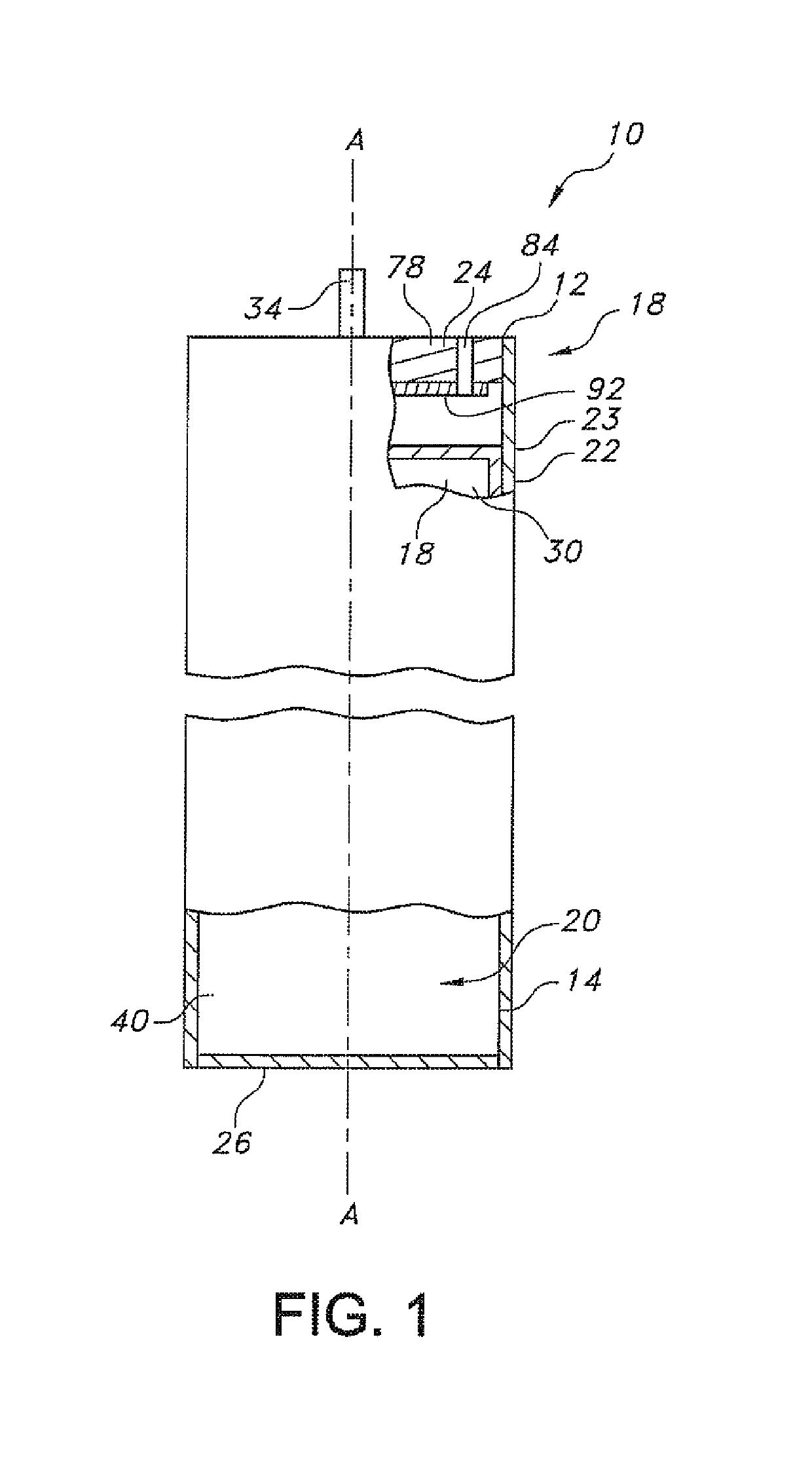
[0026]Referring now to the drawings, FIG. 1 is a partial cross-sectional view of an embodiment of an electrochemical cell 10 according to the present invention. An imaginary axis A-A extends longitudinally through the cell 10 comprising a casing 22 having a sidewall 23 extending from a proximal open end 12 to a casing distal end 14. The cell comprises an electrode assembly 16 including a cathode or positive electrode 18 and an anode or negative electrode 20 housed inside the casing 22 made of metal, such as stainless steel, titanium, nickel, aluminum, or other suitable electrically conductive material. The casing 22 preferably comprises a cylindrically shaped container that has a significantly longer length than diameter (perpendicular to the axis A-A). In other words, the casing 22 has an aspect ratio of its length to its diameter (perpendicular to its length along axis A-A) that ranges from about 2:1 to about 6:1. The casing 22 is closed at the proximal open end 12 by a header ass...


PUM

PropertyMeasurementUnit
fold angleaaaaaaaaaa
thicknessaaaaaaaaaa
timeaaaaaaaaaa

Abstract

An electrochemical cell comprising a cathode and an anode residing within a casing, the anode being positioned distal of the cathode. The cathode having a cathode current collector having an angled configuration that encourages the cathode active material to move in an axial distal direction during cell discharge. The cathode current collector may be configured having at least one fold thereby dividing the current collector into at least two portions having an angle therebetween. The cathode current collector may comprise a wire having a helical configuration or the cathode current collector may comprise a post with a thread having a helical orientation about the post exterior. A preferred chemistry is a lithium / CF.sub.x activated with a nonaqueous electrolyte.

Description

CROSS-REFERENCE TO RELATED APPLICATION[0001]This application claims priority from U.S. Provisional Application Ser. No. 62 / 348,269, filed Jun. 10, 2016.TECHNICAL FIELD[0002]This invention relates to the art of electrochemical cells, and more particularly, to a new and improved electrochemical cell construction that provides for increased energy density. The cell comprises a Group IA anode or negative electrode and a fluorinated carbon (CFx) cathode or positive electrode.BACKGROUND OF THE INVENTION[0003]Electrochemical cells provide electrical energy that powers a host of electronic devices such as external and implantable medical devices. Among the many medical devices powered by electrochemical cells are leadless pacemakers. Leadless pacemakers are typically cylindrically shaped devices that are inserted into the body through a circular catheter and attached directly to heart tissue. Leadless pacemaker devices contain both the device circuitry and electrical power source in one con...

Claims


Application Information

Patent Timeline
Patent Type & Authority Patents(United States)
IPC IPC(8): H01M4/38H01M4/78H01M6/16H01M4/583H01M4/66
CPCH01M4/382H01M6/16H01M4/661H01M4/5835H01M4/78
Inventor RUBINO, ROBERT S.LEHNES, JOSEPH M.YUN, HO-CHUL
Owner WILSON GREATBATCH LTD
Why Eureka
Try Eureka