Systems and methods for converting cryogenic liquid natural gas to high pressure natural gas and to low pressure natural gas and retain all converted product and to further dispense only by voluntary actions of the user

a technology of liquid natural gas and conversion method, which is applied in the direction of container discharging method, container filling under pressure, transportation and packaging, etc., can solve the problems of limiting the strength of containing pressure and inability to allow high pressure in containers, and achieves enhanced gasification, enhanced gasification, and enhanced thermal transfer

Active Publication Date: 2020-08-25
ANDERSON KENNETH W
View PDF11 Cites 0 Cited by
  • Summary
  • Abstract
  • Description
  • Claims
  • Application Information

AI Technical Summary

Benefits of technology

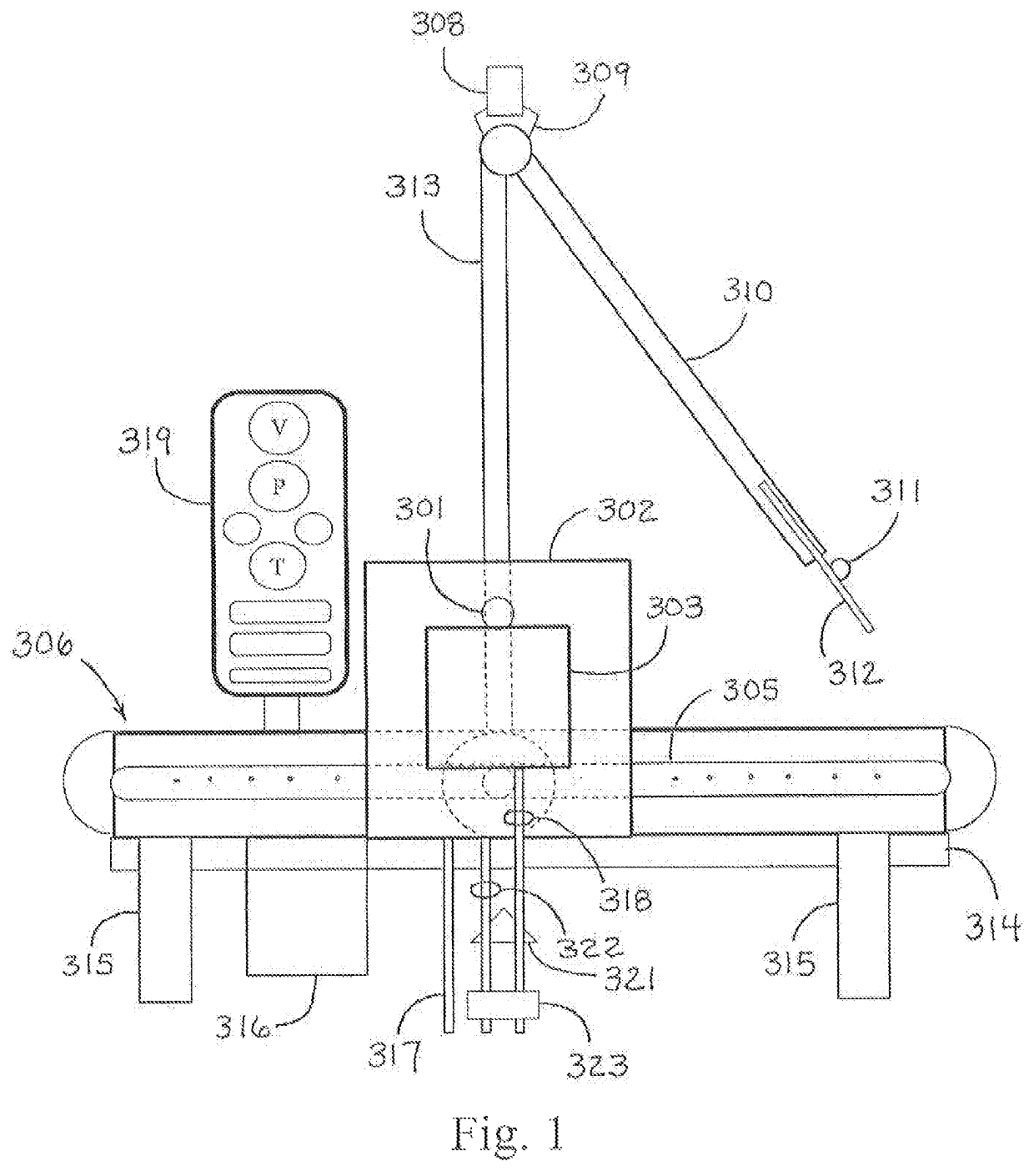
[0008]Cryogenic Liquid Gasification / Conversion. Gasification, using gas from previous conversions and containment as a heat sink. Gas from previous gasifications which is within the dedicated container further serves to aid in conversion of cryogenic liquid to gas by balancing temperatures between the density and temperature of the cryogenic liquid verses the density and temperature of the ambient gas when the result is fully contained. Gasification is also enhanced by thick walled high pressure gasifying containers which serve a dual purpose: a heat sink in the form of the shell which can be greater than one inch in thickness and is a thermal mass storage and a conduit of heat to thermal transfer and complete gasification and warming cryogenic gas toward ambient temperature. The warming conversion can occur as the result of thermal transfer using ambient temperature and lapse of time. The oval shape of the converter of one of the exemplary embodiments encourages movement of air and further enhances uniform thermal transfer. The horizontal and vertical elements of one of the exemplary embodiments provide for gravity movement of Cryogenic liquid gas such as LNG from the first cryogenic container into the second container, the gasifier container where it is converted to pressurized warm gas where it can be dispensed, without requiring a pressure building device.
[0009]Warming can also occur by using one of many types of heat sinks or other known methods. Natural gas within the system may be used for combustion to warm the thermal heat sink. Outside heat sources such as exhaust stacks or direct solar may also be used. The shape of the expansion chamber allows the thermal evolution of the heating of the LNG using horizontal and vertical elements which result in separation by temperature and density in the second container phase change converter, pressurized gas storage, and a dispensing container for multiple pressures of gas. The scale of the second container as compared to the first container and the amount of LNG delivered determine the range of the high pressure result; and retained gas from previous conversion can be used to warm the added cryogenic gas with the product of previous cycles and the ambient heat sink in the form of the containment shell while calculating the approximately 600:1 ratio of expansion of LNG as a liquid to its gas phase. Optionally, if desired, the gas movement may be mechanically, electrically, or otherwise enhanced resulting in quicker and / or more consistent system-wide warming. The stack shape of the best preferred embodiment is less expensive to construct and provides greater separation of the warm converted lower density gas production from the cold. Optional separation of gas / liquid being warmed by forced movement encourages separation enhancing gasification when desired and economically beneficial.
[0011]The system of the present invention will be used in a primary way to fuel natural gas (primarily methane) transportation vehicles such as cars, trucks, carts, lifts, cycles, etc. The present invention's CNG component can also be used as a feed stock for hydrogen production. The fuel made ready for use by the system of the present invention is superior to fuel supplied by non-LNG “natural gas” or mixed LNG sources and natural gas together, because it will be chemically more homogeneous. Water is removed. Liquid distillates, such as butane, ethane, and propane, which can settle out of methane vapor (CH4) in excess proportions, are removed in the production of LNG when they freeze or separate during the refrigeration process making a cryogenic liquid from a gas; and as a result, these impurities are prevalent in the system's fuel production in known proportions. As opposed to other fueling equipment, the fuel supplied by the system of the present invention is superior because it begins with LNG which is more homogeneous than natural gas from an older pipeline and will not begin as residential NG chemically altered with operant sulfur or other chemicals. This avoids gas streams which contain water which can foul equipment using the gas streams. The methane fuel, when used, can easily be additionally enhanced by the addition of hydrogen or other elemental gas such as Argon or Nitrogen or molecules to alter flame characteristics for custom requirements when they are desired, using the present best invention gas or liquid ports to enter the dedicated container located at the dispensing location.
[0014]This invention is scalable to allow dimensional changes which result in different beneficially targeted volumes and pressures by adjusting the ratio between the size of the first container cryogenic liquid receiver to the second container liquid to gas gasifier, taking into account the expansion ratio of the cryogenic liquid, and the target contained pressure range of the resulting gas product for increased usefulness. Adding additional dedicated second containers at a single location is anticipated, because it allows cascade dispensing, and because it allows one half of the equipment to be converting from a cryogen to a pressurized gas while the other half is dispensing. The result will always be that the first container will be smaller than the second container, and for methane, if the target pressure sought is about 3,500 psi since the expansion of methane is approximately 600:1, the size ratio between the second larger container and the first smaller container calculates to between 2-2.4:1. The invention's most beneficial scaling is in providing smaller scale use which benefits from not using semi trucks especially where their use is impractical, illegal, or unwelcome. The invention does up scale from a commercial micro dispensing size by the addition of a multiple of the same class of the on site dedicated containers. Two or three dedicated gasifier converter dispensers can be joined to accomplish cascade dispensing. Low cost CNG storage can also be easily incorporated in the process of scaling this invention but for improved security it is elevated by creating a floor supported by the upper vertical element of the dedicated container.

Problems solved by technology

Some specifications of containers do not allow high pressure, such as LNG Storage tanks where the design is such to preserve a cryogen for a month at a time by increasing insulation and decreasing thermal transfer by reducing the thickness of the container, which limits strength for containing pressure.

Method used


Image

  • Systems and methods for converting cryogenic liquid natural gas to high pressure natural gas and to low pressure natural gas and retain all converted product and to further dispense only by voluntary actions of the user
  • Systems and methods for converting cryogenic liquid natural gas to high pressure natural gas and to low pressure natural gas and retain all converted product and to further dispense only by voluntary actions of the user
  • Systems and methods for converting cryogenic liquid natural gas to high pressure natural gas and to low pressure natural gas and retain all converted product and to further dispense only by voluntary actions of the user

Examples


Embodiment Construction

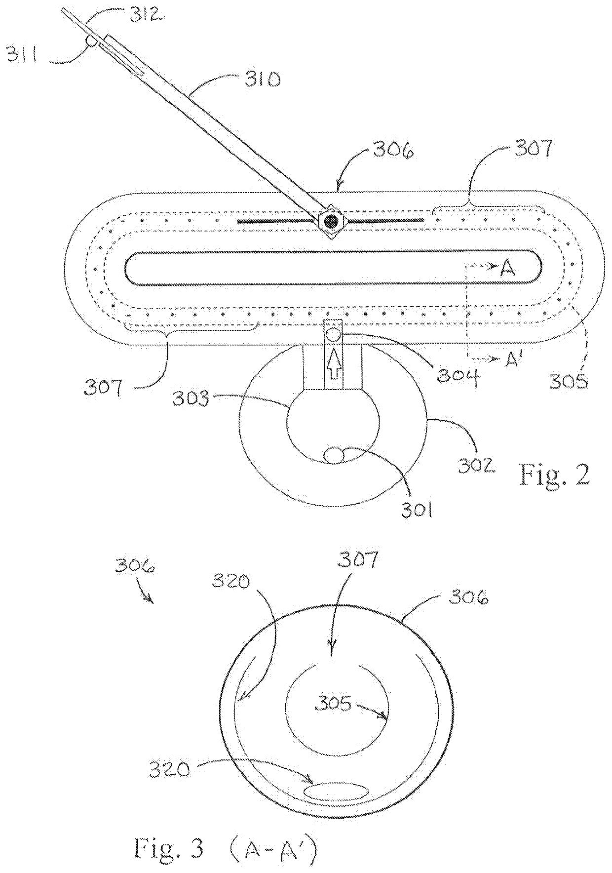
[0053]The present invention provides a LNG to CNG to NG system and method. This system may be optionally enhanced by a system generating hydrogen gas such as an electrolysis at pressure and / or at depth system. The system may also be optionally enhanced by a steam and methane reformation system, including as a heat exchange mechanism described. In the system of FIGS. 1 & 2, an oval CNG expansion chamber 2.4 times the size of the LNG cryogenic container is provided with center tube circles vented. High nickel alloy steel and some layered composites and aluminum alloys are preferably used in the construction of this system where there is contact with cryogenic liquids. The system further may include passive and / or active heat sinks. The system includes LNG fill portal 301 for the cryogenic like vessel. Also disclosed are outer container 302 and inner container 303 for the LNG Again, the approximate ratio of the container volume being 1:2.4 (41.6%) to the volume of oval pressure vessel ...


PUM


Abstract

A system to convert and dispense pressurized gas(es) of cryogenic liquids of gas(es), and systems and methods to efficiently convert liquid natural gas (LNG) to compressed natural gas (CNG) and low pressure natural gas (NG) and other cryogenic liquids of gas. The system requires one dedicated pressure vessel of horizontal and vertical elements at the dispensing location to convert, retain, store, and dispense multiple pressures of gas from a cryogenic liquid supply such as a non-dedicated high pressure cryogenic personal supply tank. The system efficiently modifies and controls parameters of volume, pressure, and temperature in conversion scale to retain all converted product under human control to dispense without process required waste for use in commercial, industrial, and in particular single family residential applications and service can be accomplished by pickup truck and trailer, where semi trucks, big rig trucks and process pollution are not welcome.

Description

CROSS REFERENCE TO RELATED APPLICATIONS[0001]This application is a continuation-in-part of U.S. patent application Ser. No. 14 / 397,457, filed Oct. 27, 2014, entitled “Systems and Methods for Converting Liquid Natural Gas to Compressed Natural Gas and to Low Pressure Natural Gas” which claims benefit of PCT / US13 / 38291, filed on Apr. 25, 2013, entitled “Systems and Methods for Converting Liquid Natural Gas to Compressed Natural Gas and to Low Pressure Natural Gas” which claims benefit of U.S. Provisional Application 61 / 637,908 filed Apr. 25, 2012.BACKGROUND OF THE INVENTION[0002]The present invention relates generally to systems for efficiently converting batches of the cryogenic liquid of a gas into a beneficial pressurized gas such as liquid natural gas (LNG) to compressed natural gas (CNG), also known as pressurized natural gas (PNG), and further to low pressure natural gas (NG). The present invention relates more specifically to a system for efficiently modifying and controlling t...

Claims


Application Information

Patent Timeline
Patent Type & Authority Patents(United States)
IPC IPC(8): F17C9/02F17C5/06
CPCF17C9/02F17C5/06F17C2201/0138F17C2201/0147F17C2201/032F17C2201/035F17C2201/05F17C2201/056F17C2201/058F17C2203/0304F17C2203/0391F17C2203/0614F17C2203/0646F17C2203/0648F17C2205/0149F17C2205/0326F17C2205/0332F17C2205/0335F17C2221/011F17C2221/012F17C2221/014F17C2221/016F17C2221/033F17C2223/013F17C2223/0161F17C2223/033F17C2225/0123F17C2225/036F17C2227/0302F17C2227/0393F17C2250/01F17C2250/036F17C2250/0426F17C2265/05F17C2270/0171F17C2270/0178F17C2270/07Y02E60/32
Inventor ANDERSON, KENNETH W.
Owner ANDERSON KENNETH W
Why Eureka
Try Eureka